Chapter 15
Device drivers
Introduction
Device drivers are the lowest layer in RadiMation®, they make it possible to communicate with thousands of different devices. They make the system flexible, while the RadiMation® Core stays generic. The RadiMation® Core does not even know which device it is controlling, only the type of device. So, if you have bought a new spectrum analyser or signal generator you only have to tell the software to use this new device and all the rest stays the same.
This chapter only describes the device driver specific configuration. All the configuration of the device drivers that are managed by the RadiMation® Core, are described in Chapter 14: 3. Device Driver configuration. Also the common device driver settings are described in Chapter 14: Device Driver Settings.
Virtual device drivers
For testing and demonstration purposes, virtual device drivers are added as well. These virtual device drivers act as a normal device but do not control real hardware.
Virtual device drivers do not have limitations like normal device drivers (like frequency band, maximum power, sweep times, etc.)
Configurable device drivers and non-configurable device drivers
RadiMation® supports two types of device drivers, configurable and non-configurable device drivers. Configurable devices for instance are powermeter, signal generators and spectrum analysers. For these devices you can set the IEEE address or the serial port which RadiMation® has to use to be able to communicate with these devices. Non-configurable devices are couplers and calibration jigs. You might think that it is useless to have non-configurable drivers, but the opposite has been proven many times. Non-configurable drivers still contain important information like the start and stop frequency of a device. With this information RadiMation® can prevent the test engineer from making large mistakes, like using the wrong coupler in a certain frequency range.
Device specific configuration
Signal generator
Pressing advanced will open an IEEE configuration screen. Please view chapter IEEE setting for a complete description. See Chapter 14: Correction files and Chapter 14: Correction file uses for correcting this device.
Amplifier
When an amplifier can be remotely controlled the specific window will appear. Please view chapter IEEE or RS232 setting for a complete description. When the amplifier can not be remotely controlled the message This Device cannot be configured will appear. See Chapter 14: Correction files and Chapter 14: Correction file uses for correcting and protecting this device.
Antenna
When pressing advanced the message This Device cannot be configured will appear because this device can not be controlled remotely. See Chapter 14: Correction files and Chapter 14: Correction file uses for correcting this device.
Coupler
When pressing advanced the message This Device cannot be configured will appear because this device can not be controlled remotely. See Chapter 14: Correction files and Chapter 14: Correction file uses for correcting this device.
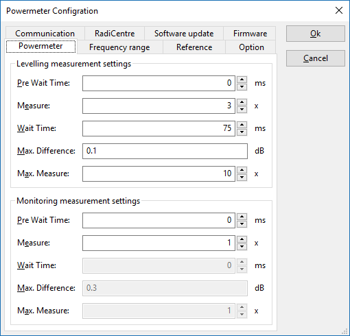
Powermeter
| The minimum time that should be waited before the measurements starts. |
| The minimum amount of measurements that RadiMation® has to perform to determine if the <Max. Difference> condition is met. |
| The minimum time that RadiMation® should be waiting between each measurement. |
| The maximum difference that is allowed between the <Measure> measurement value(s); the highest and the lowest values are compared. |
| The maximum amount of measurements that could be performed by RadiMation®, before there is a final measurement value available (which could meet these conditions, or not). |
If Measure is set to a value of 1 the Wait time, Max. Difference and Max. Measure settings will be disabled, because only one measurement will be performed.
Now that all windows have been generally explained, the procedure RadiMation® uses is the following. RadiMation® takes the amount of measurements as defined in the Measure window. After that RadiMation® determines the minimum, maximum and difference. When the difference is equal or smaller then defined in Max difference RadiMation® determines the power. If the difference is greater then defined, RadiMation® takes one new measurement. Replaces the oldest value with the new one. Determines the minimum, maximum and difference again. This continues as long as the difference is larger then defined and the maximum amount of measurement has not yet been reached. If the maximum amount of measurement has been reached the last measurement is taken as the measured value.
See Chapter 14: Correction files and Chapter 14: Correction file uses for correcting this device.
Field Sensor
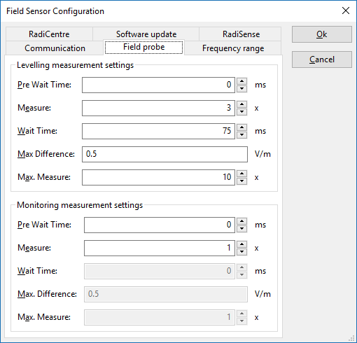
Measurement setting panel
| The minimum time that should be waited before the measurements starts. |
| The minimum amount of measurements that RadiMation® has to perform to determine if the <Max. Difference> condition is met. |
| The minimum time that RadiMation® should be waiting between each measurement. |
| The maximum difference that is allowed between the <Measure> measurement value(s); the highest and the lowest values are compared. |
| The maximum amount of measurements that could be performed by RadiMation®, before there is a final measurement value available (which could meet these conditions, or not). |
If Measure is set to a value of 1 the Wait time, Max. Difference and Max. Measure settings will be disabled, because only one measurement will be performed.
Now that all windows and buttons have been generally explained, the procedure RadiMation® uses is the following. RadiMation® takes the amount of measurements as defined in the Measure window. After that RadiMation® determines the minimum, maximum and difference. When the difference is equal or smaller then defined in Max difference RadiMation® determines the field. If the difference is greater then defined, RadiMation® takes one new measurement. Replaces the oldest value with the new one. Determines the minimum, maximum and difference again. This continues as long as the difference is larger then defined and the maximum amount of measurement has not yet been reached. If the maximum amount of measurement has been reached the last measurement is taken as the measured value.
|
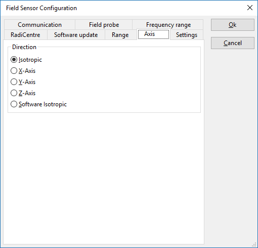
Axis setting panel
The Axis configuration is a generic driver setting panel. There are several (old) field sensors which don’t support the read out of an isotropic value: instead they provide the measurements values of all three axes separately. Using the ‘Software isotropic’ setting in the device driver can then activate that the measurement data of all three axes are being interpret and calculate to the isotropic value and have this isotropic value being return as the measured field strength. When the field sensor already supports the retrieval of the isotropic measurement value, often this value is also returned when the software option is being selected in the device configuration: both isotropic as software isotropic will return the isotropic value of the field sensor. This is depending on the device driver and used equipment.
Normally, this setting is set to ‘Isotropic’ in case the isotropic value should be returned.
AD converter
When an ad converter can be remotely controlled the specific window will appear. Please view chapter IEEE or RS232 setting for a complete description. When the ad converter can not be remotely controlled the message This Device cannot be configured will appear.
Injection device
When pressing advanced the message This Device cannot be configured will appear because this device can not be controlled remotely. See Chapter 14: Correction files and Chapter 14: Correction file uses for correcting this device.
Calibration Jigs
When pressing advanced the message This Device cannot be configured will appear because this device can not be controlled remotely. See Chapter 14: Correction files and Chapter 14: Correction file uses for correcting this device.
Current Sensor
When pressing advanced the message This Device cannot be configured will appear because this device can not be controlled remotely. See Chapter 14: Correction files and Chapter 14: Correction file uses for correcting this device.
Pre Amplifiers
When pressing advanced the message This Device cannot be configured will appear because this device can not be controlled remotely. See Chapter 14: Correction files and Chapter 14: Correction file uses for correcting this device.
Receivers / Spectrum analyser
Pressing advanced will open an IEEE configuration screen. Please view chapter IEEE setting for a complete description. See Chapter 14: Correction files and Chapter 14: Correction file uses for correcting this device.
LISN
When an LISN can be remotely controlled the specific window will appear. Please view chapter IEEE or RS232 setting for a complete description. When the LISN can not be remotely controlled the message This Device cannot be configured will appear. See Chapter 14: Correction files and Chapter 14: Correction file uses for correcting this device.
Turn Table
Pressing advanced will open an IEEE configuration screen. Please view chapter IEEE setting for a complete description.
Antenna Tower
Pressing advanced will open an IEEE configuration screen. Please view chapter IEEE setting for a complete description.
Absorbing Clamps
When pressing advanced the message This Device cannot be configured will appear because this device can not be controlled remotely. See Chapter 14: Correction files and Chapter 14: Correction file uses for correcting this device.
Clamp positioner
When a clamp positioner can be remotely controlled the specific window will appear. Please view chapter IEEE or RS232 setting for a complete description. When the clamp positioner can not be remotely controlled the message This Device cannot be configured will appear.
Cables
When pressing advanced the message This Device cannot be configured will appear because this device can not be controlled remotely. See Chapter 14: Correction files and Chapter 14: Correction file uses for correcting this device.
Switch matrix
When a switch matrix can be remotely controlled the specific window will appear. Please view chapter IEEE or RS232 setting for a complete description. When the switch matrix can not be remotely controlled the message This Device cannot be configured will appear.
EUT Controller
When a EUT Controller can be remotely controlled the specific window will appear. Please view chapter IEEE or RS232 setting for a complete description. When the EUT Controller can not be remotely controlled the message This Device cannot be configured will appear.
Communication settings
Depending on the brand and model of the device, it may be necessary to specify the parameters for the communication with the device. The GPIB/IEEE 488 and RS232 buses are most commonly used. This section describes which communication buses are supported and which communication parameters can be configured. Not all devices support all the communication buses, so only the applicable communication buses can be selected in the device driver configuration.
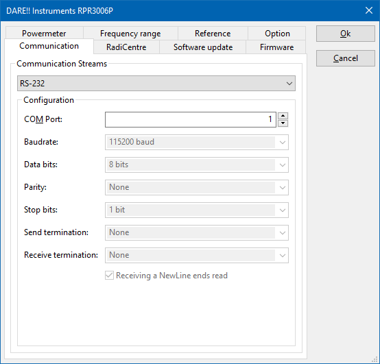
RS-232 Setting
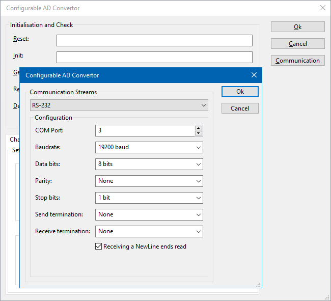
The RS-232 Communication settings are used to specify the RS-232 communication parameters, for the communication with a measurement device over RS-232. A lot of modern measurement devices are connected by USB, however very often then a Virtual RS-232 COMPort (VCP) is generated over the USB connection. In that situation also the RS-232 communication settings should configured.
| The COM port which RadiMation® has to use to be communicate with the measurement device. |
| Allows to configure the baudrate that should be used to communicate with the measurement device. This setting can be a fixed device specific value, in which case it cannot be configured and then the setting will be disabled. |
| Allows to configure the number of data bits that should be used to communicate with the measurement device. This setting can be a fixed device specific value, in which case it cannot be configured and then the setting will be disabled. |
| Allows to configure the parity bit that should be used to communicate with the measurement device. This setting can be a fixed device specific value, in which case it cannot be configured and then the setting will be disabled. |
| Allows to configure the number of stop bits that should be used to communicate with the measurement device. This setting can be a fixed device specific value, in which case it cannot be configured and then the setting will be disabled. |
| Allows to configure if and which terminator should be used during data transmissions to the measurement device. This setting can be a fixed device specific value, in which case it cannot be configured and then the setting will be disabled. |
| Allows to configure if and which terminator should be used during the receiving of data from the measurement device. This setting can be a fixed device specific value, in which case it cannot be configured and then the setting will be disabled. |
| Allows to configure if a read should be ended as soon as the receive terminator is received from the measurement device. This setting can be a fixed device specific value, in which case it cannot be configured and then the setting will be disabled. |
GPIB Setting
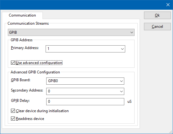
The GPIB Communication settings are used to specify the GPIB communication parameters, for the communication with a measurement device over GPIB.
| The primary address specifies the address of the device, so if the device you want to configure is on address is on 20 you enter 20. Please consult the manual of the device how to determine the GPIB address of the device. |
| Allows the end-user to enables the more advanced configuration parameters. Those advanced option should only be used if the default settings are not sufficient enough. |
| With GPIB Board you can specify the GPIB board that is used. The default value is 0 and can only be different when multiple GPIB boards are present. |
| The second address is default 0, and should only be changed when needed. For further information please look in the help of National Instruments 488.2. |
| GPIB delay is the delay between GPIB reading and writing actions. Some older IEEE 488.2 machines have difficulty communicating with fast PC's (> 2.5 GHz). This is most of the time noticeable when a driver is sometimes working and some times gives a GPIB (EABO or TIMO) error. These errors are most of the time, generated randomly. Specifying a GPIB delay time of 3000 uSeconds can fix these random errors. Run the test again and see of the problem as disappeared. Is the problem has disappear then your problem was timing, if not please contact your reseller and report the problems you are having. |
| Enabling this checkbox will send a reset to the device during initialisation. |
| Enabling this checkbox will. |
VISA Settings
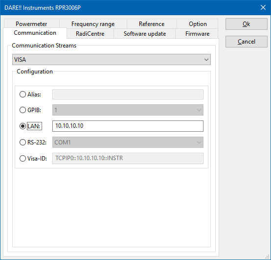
The VISA Communication settings are used to specify the VISA communication parameters, for the communication with a measurement device. The VISA library is a higher level communication library that supports different kind of communication methods. RadiMation® doesn't provide a VISA library itself, and thus requires that a VISA library from another supplier like National Instruments or Keysight Technologies is installed. The VISA manager that is provided by that VISA library can be used to determine the correct VISA resource. The selected VISA configuration thus also has influence if a measurement device is controlled by GPIB, RS-232, LAN, USB-TMC, VXI11, network-socket or another communication method .
| Allows to specify a VISA Alias that should be used for the communication with the measurement device. Any Alias that is supported by VISA is accepted. The correct Alias can be determined by using the VISA manager (eg. National Instruments MAX) that is installed on the PC. |
| Allows to specify that GPIB should be used for the communication with the measurement device. The GPIB address of the measurement device should be specified. |
| Allows to specify that a VXI11 or LXI connection should be used for the communication with the measurement device. It is possible to specify the IP-address or the (FQDN) hostname of the measurement device. |
| Allows to specify that a RS232 (ASRL in VISA terms) connection should be used for the communication with the measurement device. The COM port of the measurement device should be specified. |
Allows to specify a VISA Identifier that should be used for the communication with the measurement device. Any VISA Identifier that is supported by VISA is accepted. If one of the other communication methods is selected the corresponding VISA Identifier is also shown in this setting. Often used VISA identifiers are:
|
USB Settings
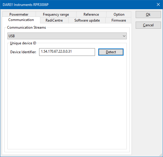
The USB Communication settings are used to specify that an USB connection to a DARE!! Instruments measurement device is used. It is not possible to use this USB communication setting for devices that simulate a Virtual COMPort (VCP) over an USB connection. The RS232 Settings should be used for such a kind of measurement device.
| The device identifier (which is an unique identifier of 8 groups of digits) that identifies the measurement device that is connected over USB. |
| Will automatically determine the correct Device Identifier for the measurement device that is connected. |
TCPIP Settings
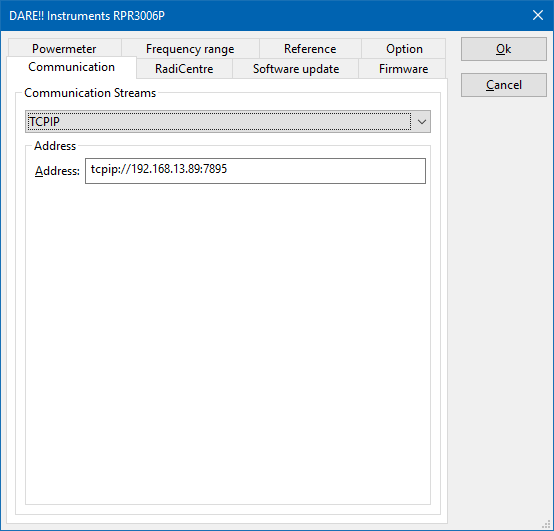
The TCPIP Communication settings are used to specify that a socket based TCPIP connection to a measurement device should be used.
| Allows to specify the IP-address or the (FQDN) hostname and the socket port number of the measurement device. This is normally done with a string like: "tcpip://<address-or-name>:<port-number>", where '<address-or-name>' is the IP address or hostname, and '<port-number>' is the socket port number on which the connection should be initiated. If the socket port number is a fixed port number, it is already shown as the default value, and it will be automatically added when no socket port number is specified. |
Virtual devices
Virtual devices are devices that act like normal devices but do not really exist. If you create a test site with only virtual devices, you can perform complete virtual tests. You might wonder why RadiMation® supports virtual device drivers. It is mainly used for debugging and solving software problems, but is has proven to be very useful when used as a temporarily workaround. For example a test site has an amplifier that is IEEE controlled and one day somebody accidentally destroys the communication between computer and amplifier. The test engineer has to perform some tests, he switches the driver for the amplifier for a virtual one. Sets the amplifier in operate by hand and was able to perform the tests that day. When the communication was repaired he changed the driver back again
Configurable devices
RadiMation® allows the user to create its own device drivers for test equipment, which is (not yet) implemented in the standard device driver list.
User configurable device drivers are available for nearly all types of test equipment. However, device drivers for spectrum analysers and measurement receivers can not be made with user configurable device drivers because the complexity (and differences between suppliers) of these devices is too high.
To make your own device driver, use the “Device drivers” tab in the “Configuration” > “Configuration” menu and follow the steps below:
- In the device driver’s menu, select the required device driver type.
- Press the “New” button.
- Select the driver called “Configurable xx” (i.e. if you want to make a signal generator device driver you would select the “Configurable signal generator” device driver).
- Enter a description for the device driver (for example the type number of the generator) and press OK.
- The name of the device driver will be added in the available device driver’s list.
- Select the new device driver from the available device device’s list.
- Press the “Edit” button.
- A configuration screen for the device driver will appear. All required control commands for the device must be entered. Refer to the operating manual of the equipment for these codes.
After all codes are entered, the device driver is ready for use.
The custom-made device driver can be used as any other device driver by selecting the driver in the Equipment list.
|
The reason for this is that RadiMation® has to know a number of parameters of these devices. Among others the following information is relevant:
- Frequency range
- Maximum input power
- The report generator needs to know which equipment is used during a test
- Correction files for these devices
Generic settings
Start and stop frequency
The most generic setting is the start and stop frequency. The default value for the start frequency is 1Hz and for the stop frequency is 40 GHz. The creator of the device is encouraged to set the right start and stop frequency. If the start and stop frequency are set correctly RadiMation® can warn the test engineer when he/she want to use the device out of its valid frequency range.
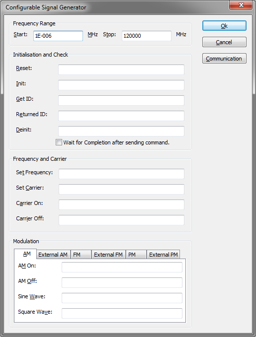
Reset
In the reset window you need to specify the string that the software needs to send when it want to reset the device. For example *RST is commonly used reset string. If you don’t know the string then leave this window blank, and make sure that the device in a neutral state.
Init
In the init window you need to specify the string that the software needs to send when it want to Init the device. For example *RST is commonly used reset string.
Get ID
In the Get ID window you need to specify the string that the software needs to send when it want to get the ID string of the device. For example *IDN? is commonly used Get ID string. Returned ID
In the Returned ID window you need to specify the string that the software will receive so that it know that it has the right device. For example "Hewlett_Packard,8643A," can be used for the Hewlett Packard 8643A. If you leave this window empty then all returned strings are accepted.
Signal generator
| Set Frequency is the string that needs to send to set the signal generator frequency. The unit is in MHZ, so the string should be made for MHz. |
Example: “FRQ__freq__MHZ”.
Example: “FRQ__freqHz__HZ”.
Example: “FRQ__freqkHz__KHZ”.
Example: “FRQ__freqMHz__MHZ”.
Example: “FRQ__freqGHz__GHZ”.
__freq__ will be replaced by the value that RadiMation® want to set the signal generator to. The “__” of “__freq__” are two “_”.
All the __freq__ keywords below, can also use the unit specifier: Hz,kHz,MHz and GHz.
| Set Carrier is the string that needs to send to set the signal generator carrierlevel. The unit is in dBm, so the string should be made for dBM. |
Example: “:SOURCE:POWER __carrier__ DBM”.
__carrier__ will be replaced by the value that RadiMation® want to set the signal generator to. The “__” of “__carrier__ ” are two “_”.
| Carrier on is the string that needs to send to set the signal generator carrier on. |
Example: “OUTPUT ON”.
| Carrier off is the string that needs to send to set the signal generator carrier off. |
Example: “OUTPUT OFF”.
| AM on is the string that needs to send to set the internal AM generator of the signal generator. The unit of frequency is KHz and the unit of Modulation Depth is %. |
Example: “SOURCE2:FREQ __freq__ KHZ;SOURCE:AM:DEPTH __depth__ PCT;SOURCE:AM:STATE ON”.
__freq__ will be replaced by the frequency and __depth__ by the modulation depth “__freq__ ” are two “_”.
| AM off is the string that needs to send to set the internal am modulation of the signal generator off. |
Example: “SOURCE:AM:STATE OFF”.
| External on is the string that needs to send to set the modulator to the external input. |
Example: “SOURCE:AM:SOURCE EXT”.
| External off is the string that needs to send to set the modulator to the internal input. |
Example: “SOURCE:AM:SOURCE INT”.
| PM on is the string that needs to send to set the internal PM generator of the signal generator. The unit of frequency is KHz and the unit of duty cycle is %. |
Example: “SOURCE2:FREQ __freq__ KHZ;SOURCE:PM:DUTY __duty__ PCT;SOURCE:PM:STATE ON”.
__freq__ will be replaced by the frequency and __duty__ by the duty cycle. “__freq__ ” are two “_”.
| PM off is the string that needs to send to set the internal PM modulation of the signal generator off. |
Example: “SOURCE:PM:STATE OFF”.
| Sine wave is the string that needs to be send when RadiMation® wants to set the wave form of the internal source to sine. |
Example: “SOURCE2:FUNC SIN”
| Square wave is the string that needs to be send when RadiMation® wants to set the wave form of the internal source to square. |
Example: “SOURCE2:FUNC SQU”
Amplifier
Only the start and stop frequency can be set for the amplifier. Chapter generic settings will give more information about the start and stop frequency.
Antenna
Only the start and stop frequency can be set for the amplifier. Chapter generic settings will give more information about the start and stop frequency.
Powermeter
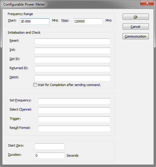
| Set Frequency is the string that needs to send to set the powermeter frequency. The unit is in MHz, so the string should be made for MHz. |
Example: “FRQ__freq__MHZ”.
__freq__ will be replaced by the value that RadiMation® want to set the powermeter too. The “__” of “__freq__” are two “_”.
| Set Select Channel is the string that RadiMation® needs to send to set the powermeter channel. This is only necessary when the powermeter has more the one channel. |
Example: “P1,U1”.
| Trigger is the string that RadiMation® needs to send to trigger the powermeter. |
Example: “X1”
| Result Format is the string that RadiMation® needs to use to decode the value from the string send by the powermeter. The return value is interpreted in dBm. |
Example: “__result__”
__result__ will be replaced by the value that RadiMation® get from the powermeter. The “__” of “__result__” are two “_”.
| Start Zero is the string that RadiMation® needs to send to start zeroing the powermeter. |
Example: “O1”
| Duration is the time that RadiMation® waits so that the powermeter can zero properly. Make sure that this time is big enough, an incorrect value may result in unpredictable result. |
Amplifier
The Configurable Amplifier device driver is a Amplifier which is supported by RadiMation®.
The configurable amplifier device driver can be used to control amplifiers for which no RadiMation® device driver is present yet. By specifying the correct commands, it is possible to send the desired commands to an amplifier. However be aware that this device driver is simple and is not able to perform more complicated tasks. Including delays and sending multiple commands at once is not possible in this device driver, a programmed device driver is needed to achieve that. Also the retrieval of the actual status of the amplifier is not supported by this configurable device driver, as the interpretation of the correct response should be very versatile.
Main
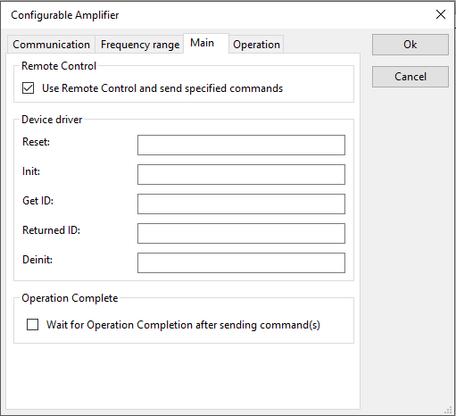
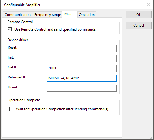
| If the checkbox is ticked, the remote control of the amplifier will be used by using the specified commands. If the checkbox is not ticked, no commands will be transmitted to the amplifier at all |
| The code that needs to be send to the device to initialize it in a defined state. When left blank, no command will be send. |
| The Init code that needs to be send to device. When left blank, no command will be send. |
| The code that needs to be send to device to get the identification back. A common used SCPI command is *IDN?. When left blank, no command will be send. |
| The code that is send back as a return on the Get ID code. When left blank, no check will be performed. |
| The Deinit code that needs to be send to device. When left blank, no command will be send. |
| If the checkbox is checked, every transmitted command will include a check to determine if the execution of the command is finished. |
Operation
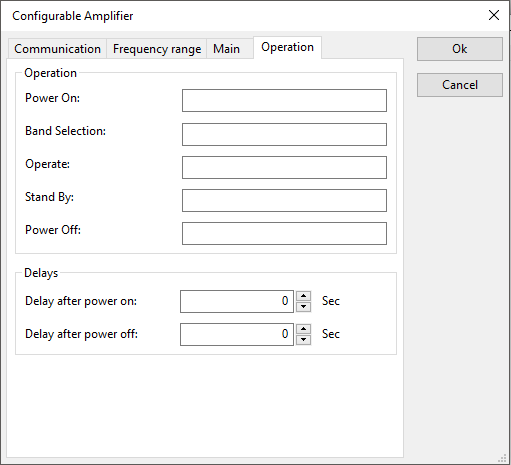
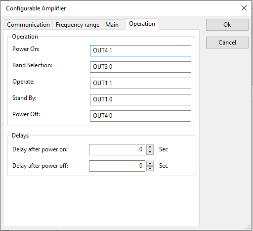
| The power on code that needs to be send to device. When left blank, no command will be send. |
| The band select code that needs to be send to device. When left blank, no command will be send. |
| The operate code that needs to be send to device. When left blank, no command will be send. |
| The standby code that needs to be send to device. When left blank, no command will be send. |
| The power off code that needs to be send to device. When left blank, no command will be send. |
| The time that must be waited after sending the power on command. |
| The time that must be waited after sending the power off command. |
Example
For this example the driver will be used to control the Milmega Controller AC-001.
Summary of control commands of Milmega Controller AC-001
| Description | Command | Parameters |
|---|---|---|
| Standby / Operate | OUT1 | 0 = RF STANDBY 1 = RF ON |
| Band Selection | OUT3 | 0 = BAND 1 1 = BAND 2 |
| Power off / on | OUT4 | 0 = LINE STANDBY 1 = LINE ON |
These commands for the Milmega AC-001 controller can be implemented in the Configurable Amplifier device driver by specifying the codes, as in the following screenshots:
AD converter
The Configurable AD Convertor device driver is a AD Converter which is supported by RadiMation®. It can be used to control other measurement equipment, for which no RadiMation device driver is available yet. The Configurable AD Convertor allows to retrieve a measurement value from the measurement equipment, where the measured value can then be used in RadiMation as an EUT Monitoring input. These values can thus be measured and shown in graphs during immunity tests.
Initialisation and Check
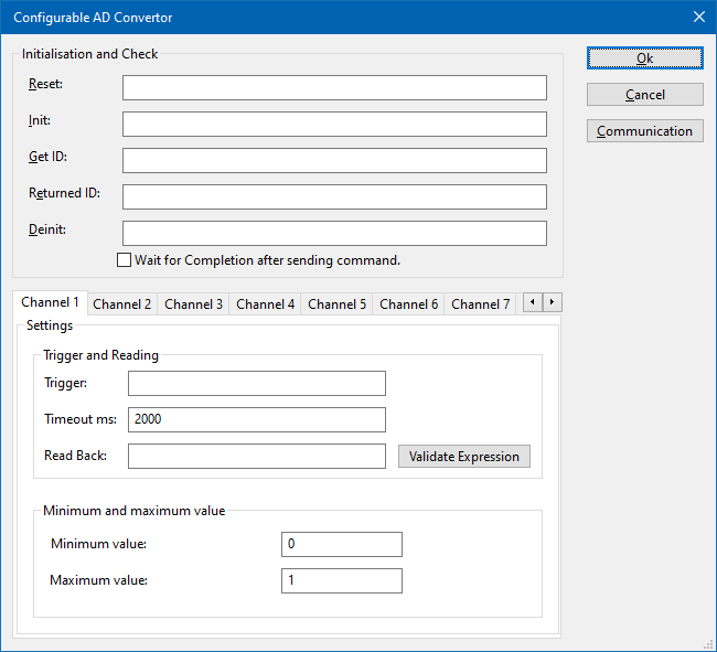
The Configurable AD Convertor device driver has several boxes, in which the remote programming commands can be specified, which should be transmitted to the measurement device on defined moments.
| The reset code that needs to be transmitted to device. When left blank, no command will be transmitted. |
| The command that is transmitted to initialise the configured device. When left blank, no command will be transmitted. |
| The query-command that is transmitted to retrieve the ID of the device. This is used to check if the device is connected. A commonly used SCPI command is: '*IDN?'. When left blank, no command will be transmitted. |
| The expected response of the device on the Get ID query. The text that is specified will be searched in the real response on Get ID query. If the specified text can be found in the response, the check for the connection is successful, otherwise it is reported that the measurement device is not connected. Leaving this blank, will skip the check if the measurement device is connected, and it is always assumed that the device is connected. |
| Specifies the command that is transmitted when the device will not be controlled anymore.This can for example be used to put the measurement device in an intrinsic safe state. When left blank, no command will be transmitted. |
| If the checkbox is ticked, RadiMation® will wait for all the commands to complete, before it continues. This is achieved by also transmitting the SCPI query-command '*OPC?' to the device, and waiting for the response. |
Channels
AD convertors can have multiple channels from which values can be read. The Configurable AD Convertor device driver is able to retrieve the values from up to 50 different channels from the measurement device. For each AD channel, an individual query-command can be specified, specific for the measurement value that should be retrieved.
The configuration of a single channel can be configured on one of the specific Channel <nr> tabs.
| The trigger query-command can be specified to trigger and request a new measurement value from the device. A commonly used SCPI query-command is: 'READ?'. |
| The timeout (specified in milliseconds) that should be used to read the response from the device. If no valid response is received within the timeout it is assumed that no value is read. |
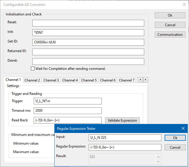
| Different measurement devices will return the measured value in different formatting. The configurable AD convertor is able to determine the numeric value of the measurement device response by using regular expressions. The text in the Read Back box, is used as the regular expressions to determine the numeric value in the response of the measurement device.
The regular expression for finding the first numeric value (including fractional and scientific notation) in a text is: ([+-]?[0-9]*\.?[0-9]+([eE][+-]?[0-9]+)?) The part of the regular expression that is contained in the round brackets, is retrieved as the measurement value and converted to a numeric value. For more possibilities see the Read Back examples section. |
| Shows a small window where the expected response of the measurement device and a regular expression can be typed. The specified regular expression will be used to interpret the specified result, and the result will be shown. This window can be used to test the regular expression, to determine if the expected response results in the desired value. |
The minimum and maximum measurable value of the measurement device can be specified to correctly scale the measured value. This will also be used to re-calculate the retrieved measurement value to another value with another unit.
| The lowest value of the channel that can be measured with the controlled measurement device. The value must be the same as filled in the EUT window. It normally is the best to configure this value to be 0. |
| The highest value of the channel that can be measured with the controlled measurement device. The value must be the same as filled in the EUT window. It normally is the best to configure this value to be 1. |
Read Back examples
Some examples for interpreting a response are:
| Received information | Regular expression | Determined measurement value | Note |
|---|---|---|---|
| U_L_N 325 | (-?[0-9.,Ee+-]+) | 325 | Takes the first number. |
| I_L1;12.34 | ;(-?[0-9.,Ee+-]+) | 12.34 | Takes the first number after ";". |
| THD_U_L1;;14,5 | ;;(-?[0-9.,Ee+-]+) | 14.5 | Takes the first number after ";;". |
| AC_FREQ;Channel1;1.23E3 | ;.*;(-?[0-9.,Ee+-]+) | 1230 | Takes the first number after the appearance of a second ";". |
The correctness of the regular expression can be tested, verified and improved by using the Validate Expression tool within the configurable device driver.
In the Regular Expression Tester, the following fields are available to verify the regular expression:
| Any text that is expected to be returned by the device. |
| The Regular expression that is being tested. This regular expression will be used to use the text from Input and convert it into a numerical value. |
| The numerical value that is determined by the device driver using the Regular Expression on the Input. |
Communication
The Configurable AD Convertor supports several communication types, which can be used to communicate with the measurement device. The Communication button can be used to open the configuration dialog to specify the actual details of the medium to use for the communication. Depending on the connection that is used, select the correct Communication Stream, and configure the parameters correspondingly to communication settings that are used by device. Different Communication Streams are available, which are described in more detail in the Communication settings section of Chapter 15.
Calibration Jigs
Only the start and stop frequency can be set for the amplifier. Chapter generic settings will give more information about the start and stop frequency
Current Sensor
Only the start and stop frequency can be set for the amplifier. Chapter generic settings will give more information about the start and stop frequency
Pre Amplifiers
Only the start and stop frequency can be set for the amplifier. Chapter generic settings will give more information about the start and stop frequency
Receivers / Spectrum analyser
Currently unavailable.
LISN
Only the start and stop frequency can be set for the amplifier. Chapter generic settings will give more information about the start and stop frequency
Turn Table
Currently unavailable.
Antenna Tower
Currently unavailable.
Absorbing Clamps
Only the start and stop frequency can be set for the amplifier. Chapter generic settings will give more information about the start and stop frequency
Clamp positioner
Currently unavailable.
Cables
Only the start and stop frequency can be set for the amplifier. Chapter generic settings will give more information about the start and stop frequency
Switch matrix
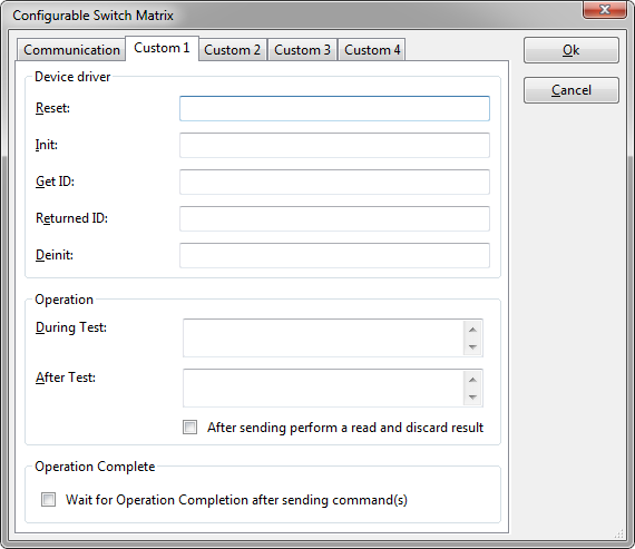
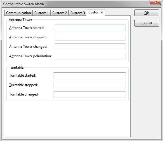
The Configurable Switch Matrix device driver is a Switch Matrix which is supported by RadiMation®.
For all text field applies: when a text field is left empty, no command is being send at that time.
|
|
|
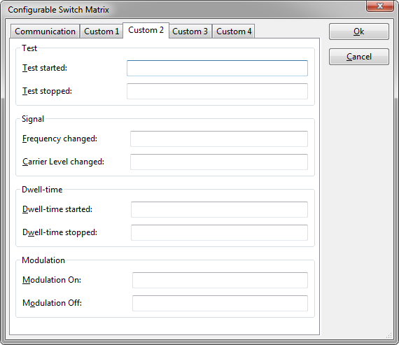
The following fields can be specified to send commands at each event. In several of the commands a keyword can be specified, which will be replaced by the actual value.
|
|
|
|
|
|
|
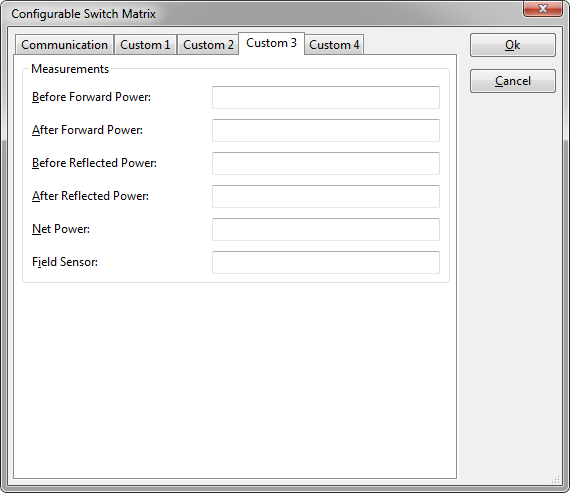
The following fields can be specified to send commands at each event. Depending on the event, the keyword __result__ can be used and is replaced by a value. For example: "My forward power is __result__dBm" will be replaced by: "My forward power is -3.15dBm".
|
The following fields can be specified to send commands at each event.
|
|
|
|
In all of the commands, it is also possible to include a keyword to insert the latest known value of another measurement value. Several keywords are available can be included in these commands. When one of these keywords is detected, it will be replaced by the corresponding value.
| keyword | inserted value |
|---|---|
| __freq__ | the signal generator frequency expressed in MHz |
| __freqHz__ | the signal generator frequency expressed in Hz |
| __freqkHz__ | the signal generator frequency expressed in kHz |
| __freqMHz__ | the signal generator frequency expressed in MHz |
| __freqGHz__ | the signal generator frequency expressed in GHz |
| __carrier__ | the signal generator carrier level expressed in dBm |
| __carrierdBm__ | the signal generator carrier level expressed in dBm |
| __carrierW__ | the signal generator carrier level expressed in Watt |
| __carriermW__ | the signal generator carrier level expressed in milli-Watt |
| __forward__ | the forward power expressed in dBm |
| __forwarddBm__ | the forward power expressed in dBm |
| __forwardW__ | the forward power expressed in Watt |
| __forwardmW__ | the forward power expressed in milli-Watt |
| __reflected__ | the reflected power expressed in dBm |
| __reflecteddBm__ | the reflected power expressed in dBm |
| __reflectedW__ | the reflected power expressed in Watt |
| __reflectedmW__ | the reflected power expressed in milli-Watt |
| __height__ | the height where the antenna is moving to expressed in metre |
| __heightm__ | the height where the antenna is moving to expressed in metre |
| __heightcm__ | the height where the antenna is moving to expressed in centimetre |
| __angle__ | the angle where the turntable is turning to expressed in degrees |
| __degree__ | the angle where the turntable is turning to expressed in degrees |
| __radian__ | the angle where the turntable is turning to expressed in radians |
Some remarks should be taken into account with these keywords:
- the keywords are case sensitive,
- the latest known value at that moment will be used,
- if no value is known at all, the keyword will not be replaced, and will remain in the command,
- the values are transmitted in non-scientific notation, and will use a '.' as a decimal point.
EUT Controller
Currently unavailable.
Messages
This Device cannot be configured
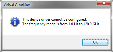
This message box is displayed when you want to edit a device driver that cannot be configured, like a coupler or calibration jig. This does not mean that the device driver is useless. Please see chapter Configurable device drivers vs. none configurable device drivers for explanation. Nowadays also information about the used configuration is showed in this message to the end-user.
Unknown Device Driver
This message box is displayed when RadiMation® is trying to locate a device driver and was unable to find it. If you see this message please contact your reseller and tell him which driver you are trying to use. The reseller will take action so that you will receive the right device driver.
GPIB: Device is not connected
This message box is displayed when RadiMation® is unable to connect to a device when using GPIB. Please check the cable and the GPIB device driver address setting.
Device not connected
This message box is displayed when RadiMation® is unable to connect to the device. Please check cables and device driver settings.
How to Report an Error
When encountering a problem with the software you might would like to report it to the RadiMation support. The RadiMation error popups, contains detailed section. This can be expanded with details button on the error popup. In the expanded detailed error popup, a Report Error button is present. This allows Error Reporting to the RadiMation support within RadiMation. More information about Error Reporting can be found here: http://wiki.dare.nl/wiki/index.php/RadiLog
AD convertors
This chapter will describe the currently supported AD convertors, there minimum and maximum value. Some drivers give different information when selecting different AD convertor channels.
National Instruments 6023E 8 Analog inputs
Type of communication: IEEE.
Channels 1:
Hewlett Packard 34401A
Type of communication: IEEE.
Channel 1
Type of measurement: AC Volt
Minimum value: 0Volt
Maximum value: 1 kVolt.
Channel 2:
Type of measurement: AC Current
Minimum value: 0 Amp.
Maximum value: 3 Amp.
Channel 3
Type of measurement: DC Volt
Minimum value: 0Volt
Maximum value: 750 Volt (rms).
Channel 4:
Type of measurement: DC Current
Minimum value: 0 Amp.
Maximum value: 3 Amp. (rms)
Channel 5
Type of measurement: Resistance (Ω)
Minimum value: 0 Ω
Maximum value: 100 MΩ
Channel 6
Type of measurement: Frequency
Minimum value: 0 Hz.
Maximum value: 300 kHz
Channel 7 and 8
Not used
Hewlett Packard 54600
Type of communication: RS 232.
Channel 1:
Type of measurement: V Max.
Minimum value: 0Volt
Maximum value: 1000 Volt.
Channel 2:
Type of measurement: V Min
Minimum value: 0 Volt.
Maximum value: 1000 Volt.
Channel 3
Type of measurement: V Average
Minimum value: 0Volt
Maximum value: 1000 Volt.
Channel 4:
Type of measurement: VPP (peak-peak)
Minimum value: 0 Volt.
Maximum value: 1000 Volt.
Channel 5
Type of measurement: Frequency
Minimum value: 0 Hz
Maximum value: 100 kHz
Channel 6
Type of measurement: Period
Minimum value: 0 ms
Maximum value: 10000 ms
Channel 7
Type of measurement: Rise Time
Minimum value: 0 ms
Maximum value: 10000 ms
Channel 8
Type of measurement: Fall Time
Minimum value: 0 ms
Maximum value: 10000 ms
Hewlett Packard 3562A
Type of communication: GPIB
Channels
All the channels give the same value back.
Minimum value: 0 dB
Maximum value: 100 dB
Hewlett Packard 59313
For all the channels is 0 is maximum negative, 1024 is zero and 2048 is maximum positive.
Type of communication: GPIB
Channel 1
Type of measurement: AD channel 1
Minimum value: 0
Maximum value: 2048
Channel 2:
Type of measurement: AD channel 2
Minimum value: 0
Maximum value: 2048
Channel 3
Type of measurement: AD channel 4
Minimum value: 0
Maximum value: 2048
Channel 4:
Type of measurement: AD channel 8
Minimum value: 0
Maximum value: 2048
Channel 5 to 8
Not used.
Hewlett Packard 59313
For all the channels is 0 is maximum negative, 1024 is zero and 2048 is maximum positive.
Type of communication: GPIB
Channels
All the channels give the same value back.
Minimum value: 0 Maximum value: 100
Marconi 2305
Type of communication: GPIB
Channel 1
Type of measurement: Frequency
Minimum value: 0
Maximum value: 1000 MHz
Channel 2:
Type of measurement: AM modulation or FM frequency Deviation
Minimum value: 0
Maximum value: 1000
Channel 3 to 8
Not used.
Fluke 45 AC Current
Type of communication: GPIB
Channels
All the channels give the same value back.
Minimum value: 0 mA
Maximum value: 10.000 mA
Fluke 45 DC Current
Type of communication: GPIB
Channels
All the channels give the same value back.
Minimum value: 0 mA
Maximum value: 10.000 mA
Fluke 45 AC Voltage
Type of communication: GPIB
Channels
All the channels give the same value back.
Minimum value: 0 mV
Maximum value: 1.000.000 mV
Fluke 45 DC Voltage
Type of communication: GPIB
Channels
All the channels give the same value back.
Minimum value: 0 mV
Maximum value: 1.000.000 mV
Fluke 45 Frequency
Type of communication: GPIB
Channels
All the channels give the same value back.
Minimum value: 0 Hz
Maximum value: 1.000.000 Hz
Fluke 45 Resistance
Type of communication: GPIB
Channels
All the channels give the same value back.
Minimum value: 0 Ω
Maximum value: 100.000.000 Ω
LeCroy 9304AM Channel A,B,C,D
Select channel A for channel A, channel B for channel B etc etc.
Type of communication: IEEE.
Channel 1
Type of measurement: Minimum value
Minimum value: 0Volt
Maximum value: 353.55 Volt.
Channel 2:
Type of measurement: Maximum value
Minimum value: 0 Volt
Maximum value: 353.55 Volt
Channel 3
Type of measurement: Amplitude
Minimum value: 0Volt
Maximum value: 353.55 Volt
Channel 4:
Type of measurement: Peak to peak
Minimum value: 0 Volt
Maximum value: 707.1 Volt
Channel 5
Type of measurement: RMS
Minimum value: 0 Volt
Maximum value: 250 Volt
Channel 6
Type of measurement: Frequency
Minimum value: 0 Hz.
Maximum value: 200 MHz
Channel 7 and 8
Not used
Fluke 8840A AC Current
Type of communication: GPIB
Channels
All the channels give the same value back.
Minimum value: 0 mA
Maximum value: 10.000 mA
Fluke 8840A DC Current
Type of communication: GPIB
Channels
All the channels give the same value back.
Minimum value: 0 mA
Maximum value: 10.000 mA
Fluke 8840A AC Voltage
Type of communication: GPIB
Channels
All the channels give the same value back.
Minimum value: 0 mV
Maximum value: 1.000.000 mV
Fluke 8840A DC Voltage
Type of communication: GPIB
Channels
All the channels give the same value back.
Minimum value: 0 mV
Maximum value: 1.000.000 mV
Hewlett Packard 3478A AC Current
Type of communication: GPIB
Channels
All the channels give the same value back.
Minimum value: 0 mA
Maximum value: 10.000 mA
Hewlett Packard 3478A DC Current
Type of communication: GPIB
Channels
All the channels give the same value back.
Minimum value: 0 mA
Maximum value: 10.000 mA
Hewlett Packard 3478A AC Voltage
Type of communication: GPIB
Channels
All the channels give the same value back.
Minimum value: 0 mV
Maximum value: 300.000 mV
Hewlett Packard 3478A DC Voltage
Type of communication: GPIB
Channels
All the channels give the same value back.
Minimum value: 0 mV
Maximum value: 300.000 mV
Tektronix TDS 400 Series
Type of communication: GPIB
Channels 1 to 4
The value of the selected channel will be given back.
Minimum value: 0
Maximum value: 100
Channels 5 to 8
Not used
Tektronix TDS 500A Series
Type of communication: GPIB
Channels 1 to 4
The value of the selected channel will be given back.
Minimum value: 0
Maximum value: 100
Channels 5 to 8
Not used
Tektronix TDS 600A Series
Type of communication: GPIB
Channels 1 to 4
The value of the selected channel will be given back.
Minimum value: 0
Maximum value: 100
Channels 5 to 8
Not used
Tektronix TDS 3000 Series
Type of communication: GPIB
Channels 1 to 4
The value of the selected channel will be given back.
Minimum value: 0
Maximum value: 100
Channels 5 to 8
Not used
DARE!! Development Radimate 2 and 3
Type of communication: RS 232
Channels 1 to 8
The value of the selected channel will be given back.
Minimum value: 0
Maximum value: 16383
EIP 575
Type of communication: IEEE
Channel 1
Type of measurement: Frequency
Minimum value: 0 Hz
Maximum value: 10 kHz
Channel 2:
Type of measurement: Frequency
Minimum value: 0 Hz.
Maximum value: 100 kHz
Channel 3
Type of measurement: Frequency
Minimum value: 0 Hz
Maximum value: 1 MHz.
Channel 4:
Type of measurement: Frequency
Minimum value: 0 Hz.
Maximum value: 10 MHz.
Channel 5
Type of measurement: Frequency
Minimum value: 0 Hz
Maximum value: 100 MHz
Channel 6
Type of measurement: Frequency
Minimum value: 0 Hz
Maximum value: 1 GHz
Channel 7
Type of measurement: Frequency
Minimum value: 0 Hz
Maximum value: 10 GHz
Channel 8
Type of measurement: Frequency
Minimum value: 0 Hz
Maximum value: 100 GHz
Parallel Port Input 0x3BC and 0x378
Channel 1 to 8
Every channel represents one bit of the 8-bits port.
So when bit 4 is changing then you will see this in channel 4.
