LeCroyOscilloscopeDeviceDriverConfiguration
|
The following tabs are available in the advanced configuration of the LeCroyOscilloscopeDeviceDriverConfiguration:
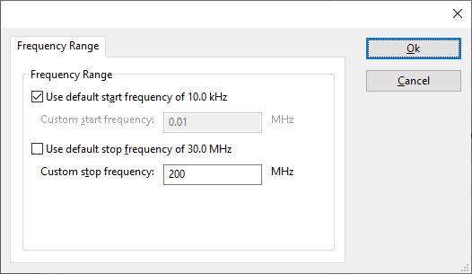
The frequency range of the LeCroyOscilloscopeDeviceDriverConfiguration as provided by the manufacturer is shown and selected as default. It is possible to overrule these frequencies and to manual adjust the allowed frequency range of the LeCroyOscilloscopeDeviceDriverConfiguration.
| If the checkbox is checked, the default start frequency will be used as the lowest usable frequency in a test for this device. |
| If the checkbox is checked, the default stop frequency will be used as the highest usable frequency in a test for this device. |
Specifying a different frequency range can be useful if for example:
- A device (like a coupler, antenna, injection device, cable, etc...) is still useable (but out of specification) outside the standard suggested frequency range.
- An external mixer is used to measure an extended frequency range.
- An up- or down-convertor is used to shift the frequency range.
- A newer model of a device is present that has an extended frequency range, and still uses the same remote control commands.
Be careful changing these setting as RadiMation® is no longer able to verify if the LeCroyOscilloscopeDeviceDriverConfiguration is used outside frequency range that is specified by the manufacturer. This may result to serious damage of your measurement device.
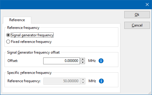
The settings on the Reference tab influence the measurement frequency that is communicated to the measurement device. The frequency that is forwarded to the measurement device can for example be used by the device to perform the measurement on the correct frequency, or use the correct internal frequency dependant correction or calibration factor on the measurement result. Normally it is desired that the measurement frequency is the same as the carrier frequency of the signal generator. In some situations it can however be required to communicate a different frequency to the measurement device. In such a situation the settings on the Reference tab can be modified.
| Selects that the actual carrier frequency of the signal generator is communicated to the measurement device. This is the default behaviour. |
| Selects that a fixed frequency (independent of the signal generator carrier frequency) is communicated to the measurement device. |
| The fixed reference frequency specified in MHz that is communicated to the measurement device, when the Fixed reference frequency option is selected. |
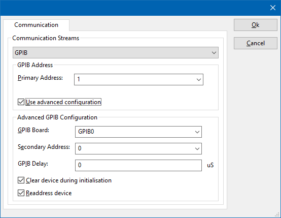
On the Communication tab, the desired communication method can be selected and configured. Depending on the selected method, additional relevant settings are shown and can be configured.
| Selects the medium or method that should be used to communicate with the device. Depending on the capabilities of the device this can be one or more of:
See the Communication Settings in Chapter 15, on how to configure each of these methods. |


