CI Calibration
Tolerance[edit]
The tolerance in the CI calibration window gives you more control over the calibration. Let say you want to calibrate 10 mA (20 dbmA), with a tolerance of 0,5 dB This would mean that all generated levels between 10 mA and 10,59254 mA are accepted as correct values. The first thing you may wonder, why not just fill in 0dB? This is possible, but will generate a large amount of warnings, because the desired levels can not be reached. 0 dB tolerance is only possible in an ideal world, and unfortunately our measuring equipment is not ideal. So, what is the correct setting? This is depending on your needs, it is always a trade off between measuring speed and accuracy. When the desired level has been reached, this level is stored inside the calibration file. Meaning, if 10 watts is generating 11 mA, then 11 mA is stored together with the 10 watts. But if I do a substitution test, will it reproduce the 11 mA again if I set it to 10 mA? The answer is no. RadiMation will calculate the power needed to achieve 10 mA and level to this value. In theory you can calibrate on 1 mA and perform testing at 100 mA, in practice you calibrate on 2 or 3 levels. For example 10 and 100 mA.
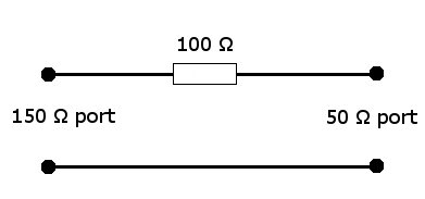
Insertion loss of the 150 Ω to 50 Ω adapter[edit]
The loss between the voltage on the 150 Ω port to the 50 Ω port is approximately 9,5 dB.
Assuming that the voltage on the 150 Ω port is 1 V, (which corresponds to 0 dBV), the voltage over the 50 Ω port is a third of the voltage of the 150 Ω port.
So, everything that is measured with a 50 Ω power sensor, is approximately 9,5 dB lower then the actual value.
Calculating the power meter reading back to Vrms in the Calibration[edit]
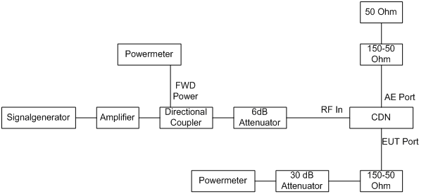
With the above picture of the calibration set up we will calculate the Vrms on the CDN.
In this example the power meter reading is -2.6 dBm.
From power to voltage:
With the known attenuation of 30 dB of the attenuator and the 15,6 dB of the 150 to 50 ohm network and e.m.f. value. The actual reading is +30.8 dBVrms.
Note:
The factor 6 (15,6 dB) arises from the e.m.f. value specified for the test level.
The matched load level is half the e.m.f. level and the further 3:1 voltage division is caused by the 150 Ω to 50 Ω adapter terminated by the 50 Ω measuring equipment.


