Current sensor transfer impedance determination method
Theory[edit]
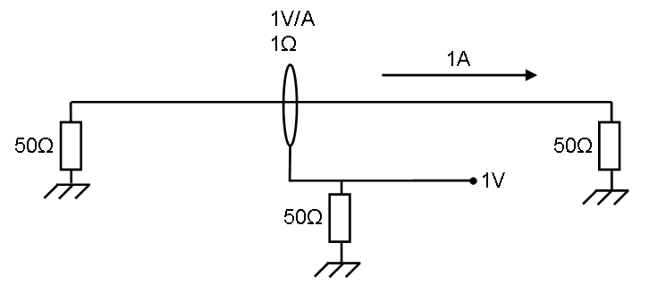
The left impedance is the signal generator which is generating enough power for 1 ampere.
This 1Amp. generates Failed to parse (SVG (MathML can be enabled via browser plugin): Invalid response ("Math extension cannot connect to Restbase.") from server "https://wikimedia.org/api/rest_v1/":): {\displaystyle P = I^2*R=50 \ Watt} in the right impedance.
The current sensor has 1 ohm transfer impedance, this means 1 ampere generates 1 Volt on the measuring part below.
The power in the lower 50 ohm impedance is Failed to parse (SVG (MathML can be enabled via browser plugin): Invalid response ("Math extension cannot connect to Restbase.") from server "https://wikimedia.org/api/rest_v1/":): {\displaystyle P = \frac{U^2}{R} = 20 \ mWatt}
So 1 ohm: Failed to parse (SVG (MathML can be enabled via browser plugin): Invalid response ("Math extension cannot connect to Restbase.") from server "https://wikimedia.org/api/rest_v1/":): {\displaystyle 10*^{10}log(\frac{0,02}{50}) \approx -33,98 dB = -20*^{10}log(50)}
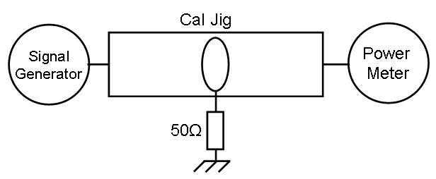
Reference measurement[edit]
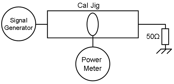
Probe measurement[edit]
Calculation[edit]
Failed to parse (SVG (MathML can be enabled via browser plugin): Invalid response ("Math extension cannot connect to Restbase.") from server "https://wikimedia.org/api/rest_v1/":): {\displaystyle Correction \ factor (dB)= P_{Measured} - P_{Reference}+ 33.98}
Failed to parse (SVG (MathML can be enabled via browser plugin): Invalid response ("Math extension cannot connect to Restbase.") from server "https://wikimedia.org/api/rest_v1/":): {\displaystyle P_{Measured}} and Failed to parse (SVG (MathML can be enabled via browser plugin): Invalid response ("Math extension cannot connect to Restbase.") from server "https://wikimedia.org/api/rest_v1/":): {\displaystyle P_{Reference}} in dBm.
Example[edit]
On 10 MHz we have the following information:
- Calibration: 0 dBm.
- Measurement: -27,96 dBm.
So: Failed to parse (SVG (MathML can be enabled via browser plugin): Invalid response ("Math extension cannot connect to Restbase.") from server "https://wikimedia.org/api/rest_v1/":): {\displaystyle Imp.=-27,96-0.00+33.98=6,02 dBOhm}
Failed to parse (SVG (MathML can be enabled via browser plugin): Invalid response ("Math extension cannot connect to Restbase.") from server "https://wikimedia.org/api/rest_v1/":): {\displaystyle Imp.\approx 2 \ Ohm}
Verification[edit]
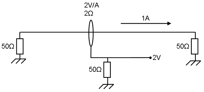
The left impedance is the signal generator which is generating enough power for 1 ampere.
This 1 Ampere generates Failed to parse (SVG (MathML can be enabled via browser plugin): Invalid response ("Math extension cannot connect to Restbase.") from server "https://wikimedia.org/api/rest_v1/":): {\displaystyle P = I^2*R=50 \ Watt} in the right impedance.
The current sensor has 2 ohm transfer impedance, this means 1 ampere generates 2 Volt on the measuring part below.
The power in the lower 50 ohm impedance is Failed to parse (SVG (MathML can be enabled via browser plugin): Invalid response ("Math extension cannot connect to Restbase.") from server "https://wikimedia.org/api/rest_v1/":): {\displaystyle P = \frac{U^2}{R} = 80 \ mWatt}
So 2 ohm: Failed to parse (SVG (MathML can be enabled via browser plugin): Invalid response ("Math extension cannot connect to Restbase.") from server "https://wikimedia.org/api/rest_v1/":): {\displaystyle 10*^{10}log(\frac{0,08}{50}) \approx -27,96 dB}
The difference to a 1 Ohm impedance is Failed to parse (SVG (MathML can be enabled via browser plugin): Invalid response ("Math extension cannot connect to Restbase.") from server "https://wikimedia.org/api/rest_v1/":): {\displaystyle -27,96 - (-33,98) = 6,02 dB}
Conclusion[edit]
Correction to a 1 ohm impedance is Failed to parse (SVG (MathML can be enabled via browser plugin): Invalid response ("Math extension cannot connect to Restbase.") from server "https://wikimedia.org/api/rest_v1/":): {\displaystyle 20*^{10}log(R_{probe})}
| Note: | This method is not a replacement for a real calibration as it may be performed by a none traceable device |


