The Keysight Technologies 34450A device driver is a AD Converter which is supported by RadiMation®.
On the Settings tab, the desired communication method can be selected and configured. Depending on the selected method, additional relevant settings are shown and can be configured.
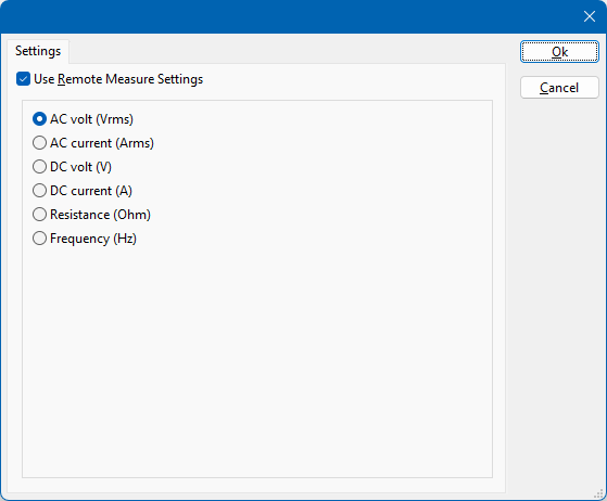
 Use Remote Measure Settings Use Remote Measure Settings
|
If selected, the Keysight Technologies 34450A will be controlled by the driver to switch to the selected measurement mode. If this option is not selected, the end-user has to manually configure the Keysight Technologies 34450A to perform the correct measurement. This manual configuration can be useful to allow the measurement of period or capacitance, if it is supported by the multimeter.
|
| AC volt (Vrms)
|
Selects the AC volt measurement mode. The measurement result will be retrieved in the volt unit.
|
| AC current (Arms)
|
Selects the AC current measurement mode. The measurement result will be retrieved in the ampere unit.
|
| DC volt (V)
|
Selects the DC volt measurement mode. The measurement result will be retrieved in the volt unit.
|
| DC current (A)
|
Selects the DC current measurement mode. The measurement result will be retrieved in the ampere unit.
|
| Resistance (Ohm)
|
Selects the resistance measurement mode. The measurement result will be retrieved in the ohm unit.
|
| Frequency (Hz)
|
Selects the frequency measurement mode. The measurement result will be retrieved in the hertz unit.
|
When the Keysight Technologies 34450A is used as an AD convertor in RadiMation®, a few of the available channels in RadiMation® can be used to retrieve the value of the selected measurement mode. As the driver for the Keysight Technologies 34450A also supports continuous background measurement during the dwell time the channel 9 and channel 10 provide additional measurement results.
- Channel 1: the last measured value of the selected measurement mode.
- Channel 9: the minimum value of the selected measurement mode since the previous measurement.
- Channel 10: the maximum value of the selected measurement mode since the previous measurement.
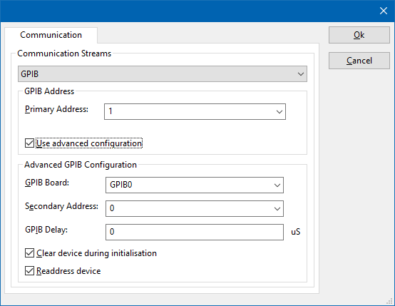
On the Communication tab, the desired communication method can be selected and configured. Depending on the selected method, additional relevant settings are shown and can be configured.
| Communication Streams
|
Selects the medium or method that should be used to communicate with the device. Depending on the capabilities of the device this can be one or more of:
Depending on the selected communication stream, additional configuration parameters can be configured. See the Communication Settings in Chapter 15, on how to configure each of these communication streams.
|
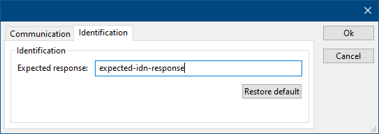
On the Identification tab, the expected *IDN? response of the test and measurement device can be configured. It is used to determine if the correct test and measurement device is connected.
| Expected response
|
The expected *IDN? response of a device. It can be changed in the case the commands are the same for another device for which no RadiMation® driver is available yet.
|
| Restore default
|
Restores the original Exepected response.
|


