
|
Note:
|
This page is used to show the configuration of the Raditeq antenna tower related device drivers. This page can now easily be embedded on all relevant device driver pages.
|
Configuration[edit]
The following tabs are available in the advanced configuration of the RadiAntennaTowerDeviceDriverConfiguration:
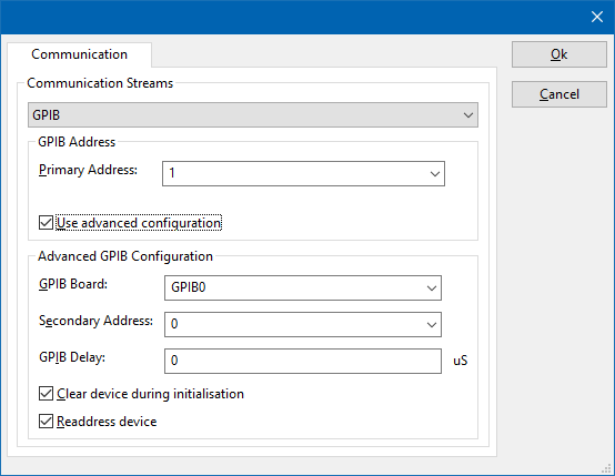
On the Communication tab, the desired communication method can be selected and configured. Depending on the selected method, additional relevant settings are shown and can be configured.
 Communication Streams Communication Streams
|
Selects the medium or method that should be used to communicate with the device. Depending on the capabilities of the device this can be one or more of:
Depending on the selected communication stream, additional configuration parameters can be configured. See the Communication Settings in Chapter 15, on how to configure each of these communication streams.
|
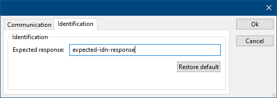
On the Identification tab, the expected *IDN? response of the test and measurement device can be configured. It is used to determine if the correct test and measurement device is connected.
| Expected response
|
The expected *IDN? response of a device. It can be changed in the case the commands are the same for another device for which no RadiMation® driver is available yet.
|
| Restore default
|
Restores the original Exepected response.
|
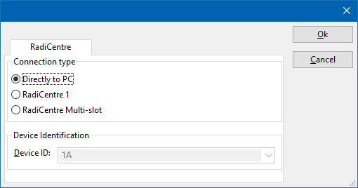
There are several methods in which the RadiAntennaTowerDeviceDriverConfiguration can be connected to the PC. The RadiAntennaTowerDeviceDriverConfiguration can for example be connected directly to the PC, or through a plugincard in a RadiCentre 1 or a multi-slot RadiCentre. More information on how to use the RadiCentre is present in the product manual of the RadiCentre. The settings on the RadiCentre tab can be used to specify how the RadiAntennaTowerDeviceDriverConfiguration is connected.
When the RadiAntennaTowerDeviceDriverConfiguration is connected to a multi-slot RadiCentre, also the slot number in which the plugincard is fitted, should be specified.
| Directly to PC
|
Specifies that the RadiAntennaTowerDeviceDriverConfiguration is connected directly to the PC, without the use of a RadiCentre.
|
| RadiCentre 1
|
Specifies that the RadiAntennaTowerDeviceDriverConfiguration is connected to a plugincard that is fitted in a RadiCentre 1.
|
| RadiCentre multi-slot
|
Specifies that the RadiAntennaTowerDeviceDriverConfiguration is connected to a plugincard that is fitted in a multi-slot RadiCentre that also can be manually controlled using the display on the front of the RadiCentre. The slot number in which the plugin card is mounted can also be selected.
|
| RadiCentre multi-slot Ultra
|
Specifies that the RadiAntennaTowerDeviceDriverConfiguration is connected to a plugincard that is fitted in a multi-slot RadiCentre Ultra. This RadiCentre Ultra has no display, and can only be used when remote controlled.
|
The settings on this RadiCentre tab, only specifies if and which RadiCentre is used. The communication settings on the Communication tab specify the connection settings to communication with the measurement device.
The configuration on the Communication tab should be configured depending on the outgoing connection from the PC. Thus if Directly to PC is selected, the communication settings should be configured as what is actually used between the PC and the RadiAntennaTowerDeviceDriverConfiguration itself. If RadiCentre 1, RadiCentre multi-slot or RadiCentre multi-slot Ultra is selected, the communication settings should be configured as what is actually used between the PC and the RadiCentre. In the configuration where a RadiPower is connected with USB to a multi-slot RadiCentre, which is connected by GPIB to the PC, the communication settings of the RadiPower device driver should thus be GPIB.
If the RadiAntennaTowerDeviceDriverConfiguration is for example connected to slot 3 of a multi-slot RadiCentre which has IP address 192.168.178.95 and is connected by LAN to the PC, the following settings should be configured in the device driver of the RadiAntennaTowerDeviceDriverConfiguration:
- RadiCentre tab
- Connection type: RadiCentre multi-slot, using as slot number: 3
- Communication tab
- Communication Stream: VISA
- LAN: 192.168.178.95
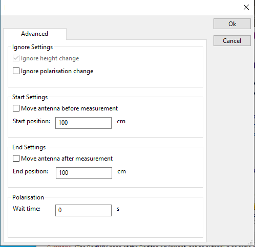
The following settings can be changed for the advanced antenna tower drivers
| Ignore height change
|
Indicate that height changes must be ignored.
|
| Ignore polarisation change
|
Indicate that polarization changes must be ignored.
|
| Move antenna before measurement
|
Indicate that the antenna height must be changed before the test is started.
|
| Start position
|
The position to which the antenna tower must be moved before the test is started.
|
| Move antenna after measurement
|
Indicate that the antenna height must be changed after the test is finished.
|
| End position
|
The position to which the antenna tower must be moved after the test is finished.
|
| Wait time
|
The time that must be wait when changing the polarisation.
|
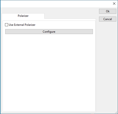
The polarizer of the RadiAntennaTowerDeviceDriverConfiguration can be configured to use an external polarizer.
| Use external Polarizer
|
Indicate that an external polarizer is used.
|
| Configure
|
Configure the settings of the external polarizer.
|
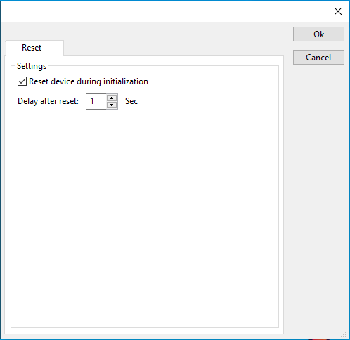
The device driver can be configured to be reset on initialization.
| Reset device during initialization
|
Configure that the device is reset when initialized.
|
| Delay after reset
|
The time in seconds to wait after resetting the device
|
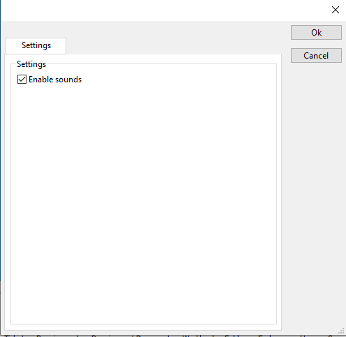
Some polarizers have additional settings that can be configured these are shown on the settings panel
| Enable sounds
|
Enable or disable sound coming from the polarizer.
|
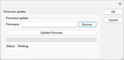
The Firmware update tab can be used to update the firmware of the RadiAntennaTowerDeviceDriverConfiguration.
| Firmware
|
Specifies the filename of the firmware update file that should be used to update the firmware of the measurement device.
|
| Browse
|
Allows to select the firmware update file.
|
| Update firmware
|
Starts the actual firmware update. First some checks are performed, and if those checks are successful, the actual firmware update is performed.
|
| Status
|
Shows a message during the firmware update, indicating the performed action and the actual status.
|

|
Warning:
|
The firmware update can take a few minutes. During the actual firmware update the window is disabled, and cannot be closed. It is possible that Microsoft Windows shows messages that the RadiMation® software is not responding. Ignore those messages and do not kill, abort or end the software. Also do not disconnect the connection between the RadiAntennaTowerDeviceDriverConfiguration and the PC, while the firmware update is being performed.
|
After the firmware update is completed, a messagebox will be shown that the firmware update has been completed successfully. In the case that an error has occurred, this will also be shown. In case that an error has been detected, it is strongly suggested to directly use the RadiMation® Error Report function to report the error to Raditeq.


