How to perform a MIL-STD-461 CE102, Conducted Emissions, radio frequency potential, power leads test[edit]
This application note explains how the MIL-STD-461 CE101, Conducted Emissions, radio frequency potential, power leads test can be performed with RadiMation®.
The exact requirements and test methods for the CE102 are specified in the MIL-STD-461.
Necessary equipment[edit]
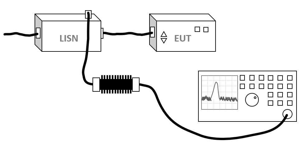
The following devices are necessary to execute this test:
- Receiver
- LISN
- Attenuator
- Cable
Configuration of the test sites[edit]
The configuration of the equipment is a lisn connected with a cable to a receiver with a attenuator of 20 dB.
The configuration of the test site should contain the following devices:
| Device name |
Tab in testsite configuration window |
note
|
| LISN |
Devices 2 |
LISN
|
| Spectrum Analyser |
Devices 2 |
The receiver used for the test
|
| Cable preamp -> analyser |
Cables |
Cable with a correction file specified for the cable loss
|
| Cable preamp -> analyser |
Cables |
Cable with the specified loss of the used attenuator
|
Perform the test[edit]
To perform the actual CE102 test, start a Conducted Emission Multiband test:
-
 Tests
Tests
- Conducted Emission
- Multiband
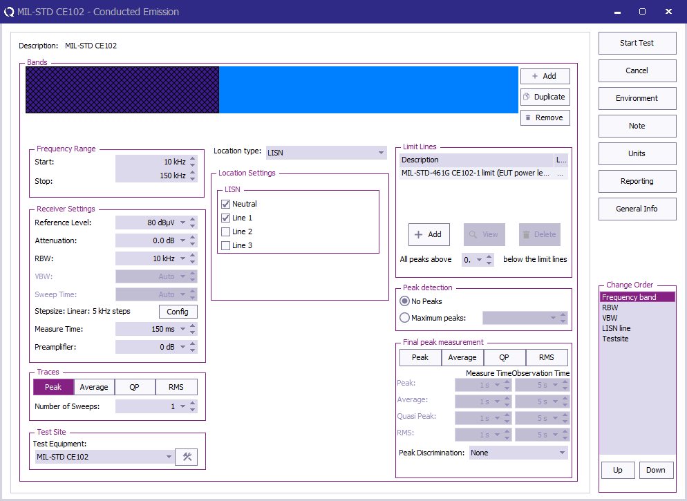
The complete test from 10 kHz up to 10 MHz has different settings for different frequency bands. All these different bands can be configured.
The test can be configured with 2 bands, each using their applicable frequency range, measure time and bandwidth.
| Band |
Frequency range |
RBW |
Step size |
Measure time receiver |
Measure time FFT receiver
|
| Band 1 |
10 kHz - 150 kHz |
10 kHz |
5 kHz |
0.015 s |
1 s
|
| Band 2 |
150 kHz - 10 MHz |
10 kHz |
5 kHz |
0.015 s |
0.15 s
|
In the following test configuration an EUT for "EUT power leads, AC and DC, for all applications" is tested.
 Start Start
|
The start frequency of the test. For example 10 kHz.
|
| Stop
|
The stop frequency of the test. For example 10 MHz.
|
| Reference Level
|
The reference level set in an analyser, not used in a receiver
|
| Attenuation
|
The attenuation set in the receiver
|
| RBW
|
The RBW set in the receiver, see table with different bands for possible values
|
| Step size
|
The step size set in the receiver, see table with different bands for possible values
|
| Measure time
|
The measure time set in the receiver, see table with different bands for possible values
|
| Preamplifier
|
The preamplifier setting set in the receiver
|
| Traces
|
The type of trace set in the receiver, for MIL-STD-461 CE102 a peak detector is used
|
| Test Equipment
|
The equipment used for the measurement, see table with different bands for possible values
|
| Location type
|
Set this to "LISN"
|
| LISN
|
Select the LISN line(s) to test
|
| Limit Lines
|
The applicable limit line can be added, in this case "MIL-STD-461G CE102-1 (EUT power leads, AC and DC) for all applications"
|
| All peaks above x dB below the limit line
|
Which level above x dB below the limit line should detect peaks, no final peaks should be measured in MIL-STD-461 CE102
|
| Peak detection
|
How many peaks should be detected automatically, no final peaks should be measured for MIL-STD-461 CE102
|
| Final peak measurement
|
It is possible to perform a final measurement on a peak with a specific detector, no final peak measurement is needed for CE102
|
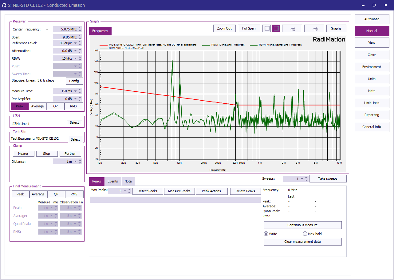
When all parameters are configured for the CE102 test, press Start Test to perform the conducted emission measurement.
Review the measurement[edit]
Once the test is finished, the results of this test are stored in the EUT file and available as one of the performed Tests in the EUT file. Selecting the corresponding test result and pressing on Info will show the test results again.
Conclusion[edit]
The MIL-STD-461 CE102 test is using different receiver settings depending on the frequency band. All these settings can be easily configured in a "Test Setup File" and tested with RadiMation®.


