How to perform a MIL-STD-461 CS114, Conducted susceptibility, bulk cable injection test[edit]
This application note explains how the MIL-STD-461 CS114, Conducted susceptibility, bulk cable injection test can be performed with RadiMation®
CS114 is a test method used in military and aerospace environments to assess the susceptibility of electronic equipment to conducted RF (radio frequency) currents over a frequency range of 10 kHz to 200 MHz. The test uses pulse modulation to ensure that devices can withstand conducted interference without experiencing performance degradation or failure.
The exact requirements and test methods for the CS114 are specified in the MIL-STD-461.
Necessary equipment[edit]
The following devices are necessary to run the calibration, verification and EUT test:
- Signal generator
- Amplifier
- Coupler
- Forward power meter
- Current sensor
- Sensor power meter / Analyser
- 50 Ohm load
- 50 Ohm attenuator
- Current injection device
- Current injection calibration jig (Calibration fixture)
- Cable drivers with corrections

|
Note:
|
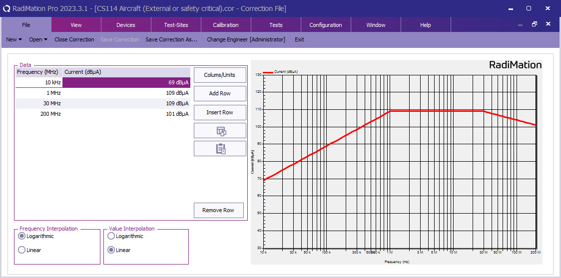
If the current unit is shown as μA, it can be changed to dBμA by clicking Units, select Current and click Edit to change this.
|
Define the test level[edit]
CS114 uses a limit that varies over the frequency range and therefor we have to configure a variable test level.
These limits are configured with a correction file in RadiMation®.
-
 File
File
- New
- Correction
First create a correction file in RadiMation® and specify the applicable test level (See 'TABLE IV CS114 limit curves.' and 'FIGURE CS114-1. CS114 calibration limits.' of the MIL-STD-461.).
In this example the limits for 'Aircraft (External or safety critical) / Curve 5 are configured.
Ensure that the correction file has a Frequency column and a Current column with the unit set to dBμA.
- File
- Save correction
Store the test level as correction file on disk.
This correction file with the test level will be used during the calibration, verification and the EUT testing.
Calibration procedure[edit]
The calibration is performed to characterize the losses and determine the correct power level in the used measurement setup.
Calibration equipment[edit]
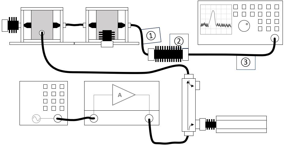
The configuration of the calibration test site should contain the following devices:
| # |
Device name |
Tab in testsite configuration window |
note
|
|
Signal Generator |
Devices 1 |
The signal generator to use
|
|
Amplifier |
Devices 1 |
The amplifier to use
|
|
Coupler |
Devices 1 |
The coupler to use
|
|
Forward power meter |
Devices 1 |
The forward power meter to use
|
|
Sensor powermeter |
Devices 2 |
The power meter or analyser to use for measuring the current
|
|
Current Sensor |
Devices 2 |
The current sensor to use with transfer factor attached to the driver
|
|
Injection device |
Devices 2 |
The injection clamp to use
|
|
Jig |
Devices 2 |
The jig to use
|
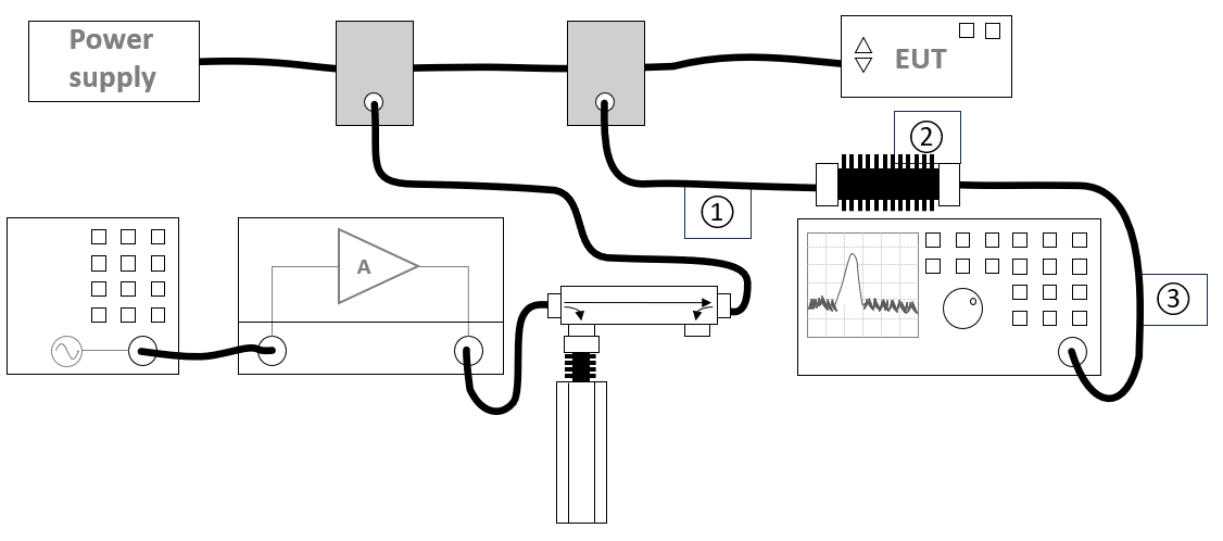
| Cables
|
| ① |
Cable current -> power meter |
Cables |
Cable with a correction file specified for the cable loss
|
| ② |
Cable current -> power meter |
Cables |
Cable with the specified loss of the used attenuator
|
| ③ |
Cable current -> power meter |
Cables |
Cable with a correction file specified for the cable loss
|
Configure the calibration[edit]
There are three frequency ranges that have to be calibrated with the following settings (see TABLE III in MIL-STD-461.).
| Band |
Frequency range |
Step size
|
| Band 1 |
10 kHz - 1 MHz |
5 %
|
| Band 2 |
1 MHz - 30 MHz |
1 %
|
| Band 2 |
30 MHz - 200 MHz |
0.5 %
|
These three bands can be configured and performed in three different calibrations. The calibration can be started from the menu by selecting:
- Calibration
- System calibration
- Conducted immunity
This example shows the configuration for band 1, a similar configuration can be created for the other bands.
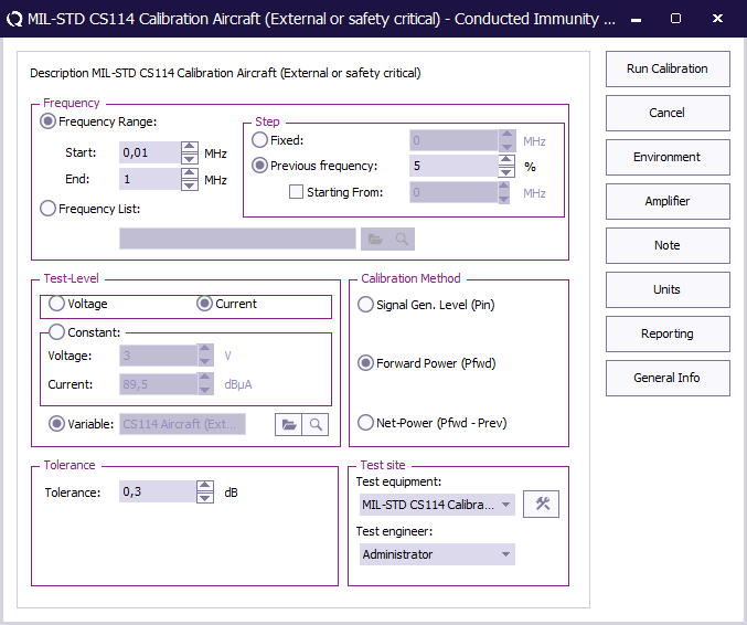
 Start Start
|
The start frequency of the calibration. For example 10 kHz.
|
| End
|
The stop frequency of the calibration. For example 1 MHz.
|
| Step
|
The frequency step, in this case 5%.
|
| Test level
|
The test level, in this case current.
|
| Variable
|
The variable test level, select the correction file created earlier.
|
| Tolerance
|
The regulation tolerance.
|
| Calibration method
|
The power measurement that should be the result of the calibration: Forward power
|
| Test equipment
|
Calibration test equipment.
|
| Test engineer
|
The engineer that performed the calibration.
|
Calibration result[edit]
When the calibration is performed, the engineer is asked, to save the results of that calibration to a calibration (.CAL) file. It is possible to give the .CAL file any clear and distinct name. All three bands have to calibrated, and at the end, there should be three different calibration files that are generated.
Verification[edit]
CS114 requires to perform a verification of the setup with the current probe in the calibration setup. With this verification it is important to verify that the forward power of the calibration is followed and that the generated current is within 3 dB tolerance of the current test limit.
Verification equipment[edit]
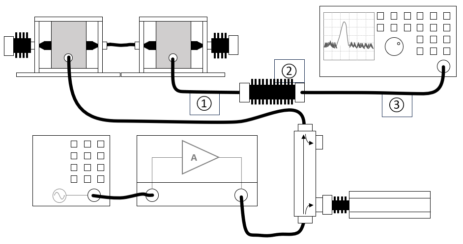
The configuration of the verification test site should contain the following devices:
| # |
Device name |
Tab in testsite configuration window |
note
|
|
Signal Generator |
Devices 1 |
The signal generator to use
|
|
Amplifier |
Devices 1 |
The amplifier to use
|
|
Coupler |
Devices 1 |
The coupler to use
|
|
Forward power meter |
Devices 1 |
The forward power meter to use
|
|
Sensor powermeter |
Devices 2 |
The power meter or analyser to use for measuring the current
|
|
Current Sensor |
Devices 2 |
The current sensor to use with transfer factor attached to the driver
|
|
Injection device |
Devices 2 |
The injection clamp to use
|
| Cables
|
| ① |
Cable current -> power meter |
Cables |
Cable with a correction file specified for the cable loss
|
| ② |
Cable current -> power meter |
Cables |
Cable with the specified loss of the used attenuator
|
| ③ |
Cable current -> power meter |
Cables |
Cable with a correction file specified for the cable loss
|
Configure the verification[edit]
The verification can be performed in RadiMation® by doing an actual conducted immunity test. This test can be started by selecting from the menu:
- Tests
- Conducted Immunity
- Multiband
Create a new multiband conducted immunity test and define three bands with the following settings:
| Band |
Frequency range |
Step size
|
| Band 1 |
10 kHz - 1 MHz |
10 %
|
| Band 2 |
1 MHz - 30 MHz |
2 %
|
| Band 2 |
30 MHz - 200 MHz |
1 %
|
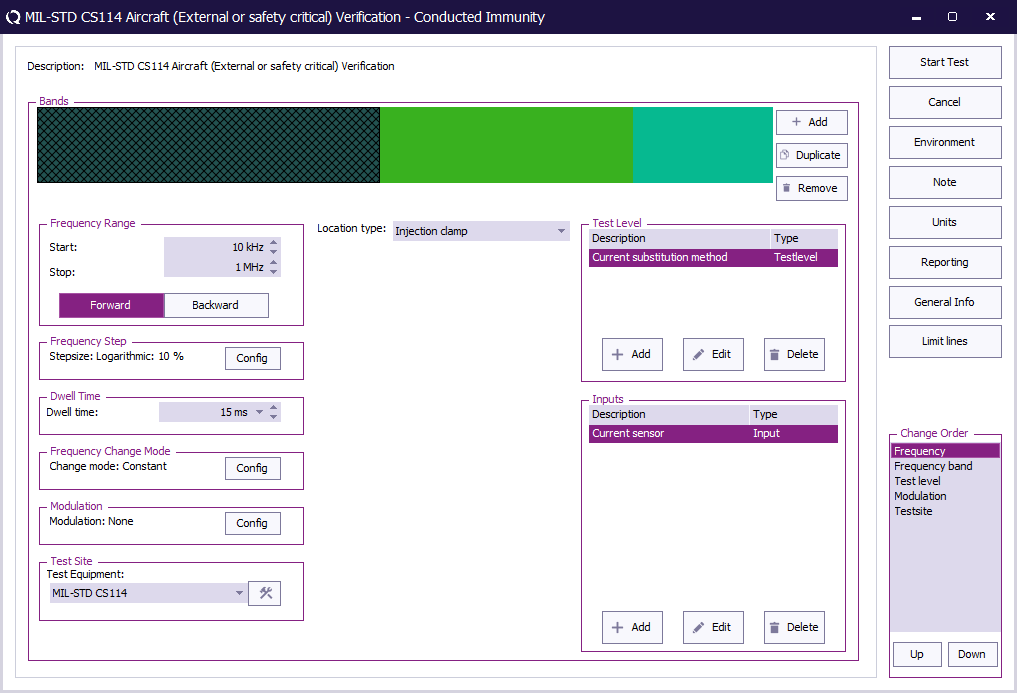
| Start
|
The start frequency of the verification. For example 10 kHz.
|
| End
|
The stop frequency of the verification. For example 1 MHz.
|
| Frequency Step
|
The frequency step, see 5.12.3.4.c.3.
|
| Dwell Time
|
The dwell time specified see TABLE II of the MIL-STD-461.
|
| Frequency Change Mode
|
The method that is used to change from one to the next frequency: Constant.
|
| Modulation
|
Modulation is optional during the verification.
|
| Test equipment
|
The equipment needed for the verification.
|
| Location Type
|
Injection clamp.
|
| Test Level
|
Specify the test level Current substitution method.
|
| Inputs
|
Add the Current sensor as an input.
|
Each band needs a test level defined with the test level Current substitution method and the appropriate calibration file attached.
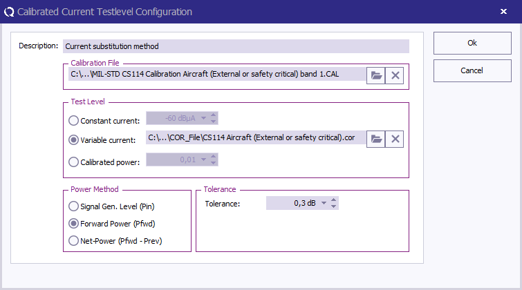
| Description
|
The description of the test level.
|
| Calibration file
|
Select the calibration file created during the calibration procedure.
|
| Test level
|
Variable current and specify the correction file for the applicable test level created during the calibration procedure.
|
| Calibration method
|
Select Forward Power.
|
| Tolerance
|
Specify the tolerance to use.
|
Add an input Current sensor, this will ensure that the current is measured during the test.
Run the verification test[edit]
When all settings are configured press Start Test to run the verification test.
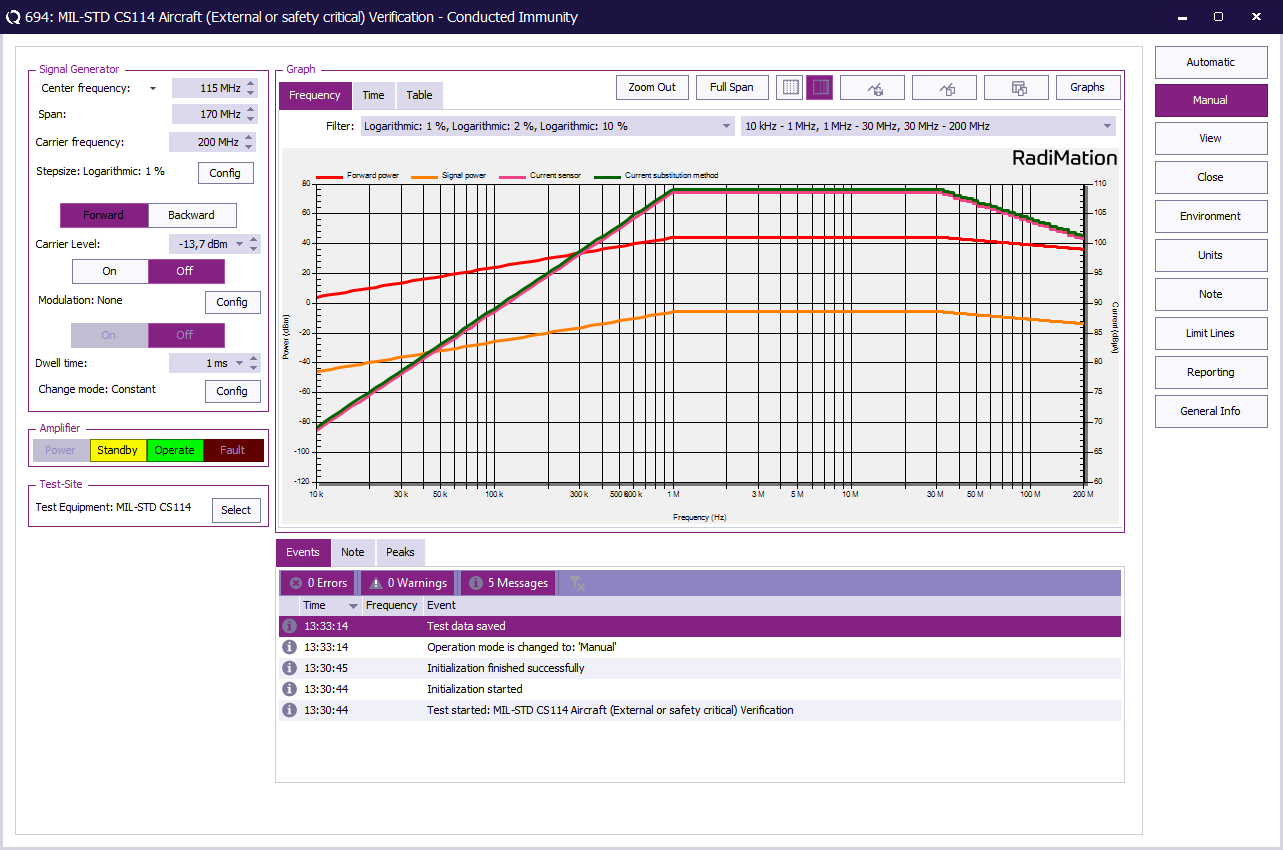
Verification result[edit]
With the result of the verification it should be possible to determine if the measured current is within the 3 dB tolerance of the current test limit as specified in clause 5.12.3.4.c of the MIL-STD-461.
EUT Testing[edit]
EUT Testing equipment[edit]
The configuration of the eut test site should contain the following devices:
| # |
Device name |
Tab in testsite configuration window |
note
|
|
Signal Generator |
Devices 1 |
The signal generator to use
|
|
Amplifier |
Devices 1 |
The amplifier to use
|
|
Coupler |
Devices 1 |
The coupler to use
|
|
Forward power meter |
Devices 1 |
The forward power meter to use
|
|
Sensor powermeter |
Devices 2 |
The power meter or analyser to use for measuring the current
|
|
Current Sensor |
Devices 2 |
The current sensor to use with transfer factor attached to the driver
|
|
Injection device |
Devices 2 |
The injection clamp to use
|
| Cables
|
| ① |
Cable current -> power meter |
Cables |
Cable with a correction file specified for the cable loss
|
| ② |
Cable current -> power meter |
Cables |
Cable with the specified loss of the used attenuator
|
| ③ |
Cable current -> power meter |
Cables |
Cable with a correction file specified for the cable loss
|
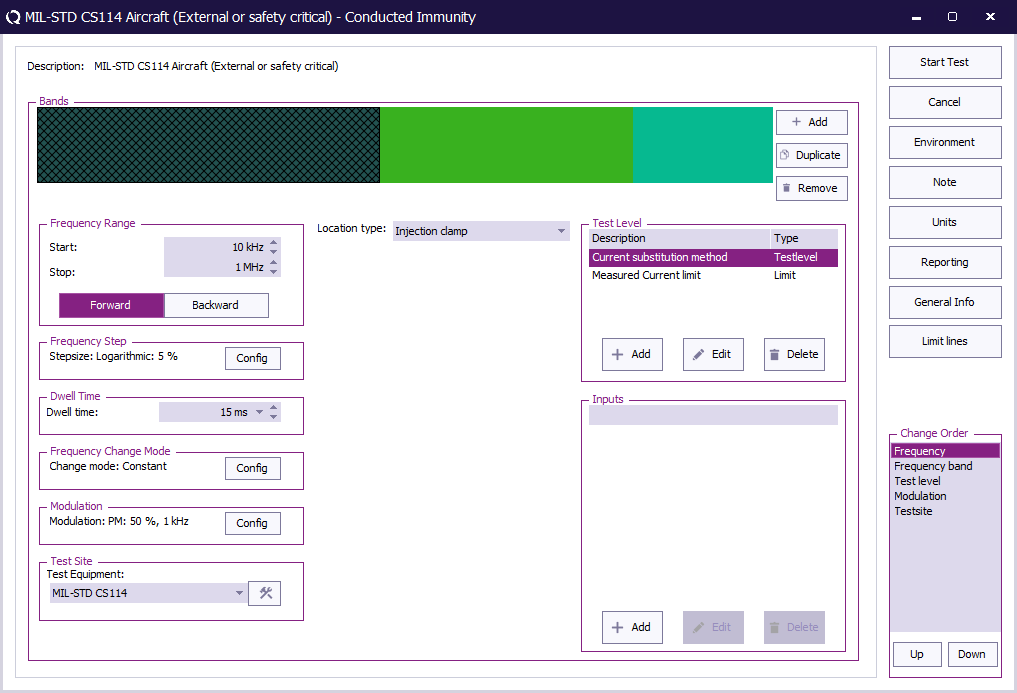
Configure the EUT test[edit]
To perform the actual test on the EUT, create a conducted immunity multiband test with 3 bands.
The conducted immunity multiband test, can be started by selecting from the menu:
- Tests
- Conducted Immunity
- Multiband
The following bands should be configured.
| Band |
Frequency range |
Step size
|
| Band 1 |
10 kHz - 1 MHz |
5 %
|
| Band 2 |
1 MHz - 30 MHz |
1 %
|
| Band 2 |
30 MHz - 200 MHz |
0.5 %
|
| Start
|
The start frequency of the test. For example 10 kHz.
|
| End
|
The stop frequency of the test. For example 1 MHz.
|
| Frequency Step
|
The frequency step, see Table III.
|
| Dwell Time
|
The dwell time specified see TABLE II of the MIL-STD-461.
|
| Frequency Change Mode
|
The method that is used to change from one to the next frequency: Constant.
|
| Modulation
|
Configure Pulse Modulation with 1 kHz and 50% duty cycle.
|
| Test equipment
|
The equipment needed for the conducted immunity test.
|
| Location Type
|
Injection clamp.
|
| Test Level
|
Specify the Current substition method and add a limit Measured Current Limit
|
| Inputs
|
No inputs are needed.
|
To configure the pulse modulation settings click Config next to the modulation settings, click the PM tab, and enter the pulse modulation settings as defined in 5.12.3.4.d.1.
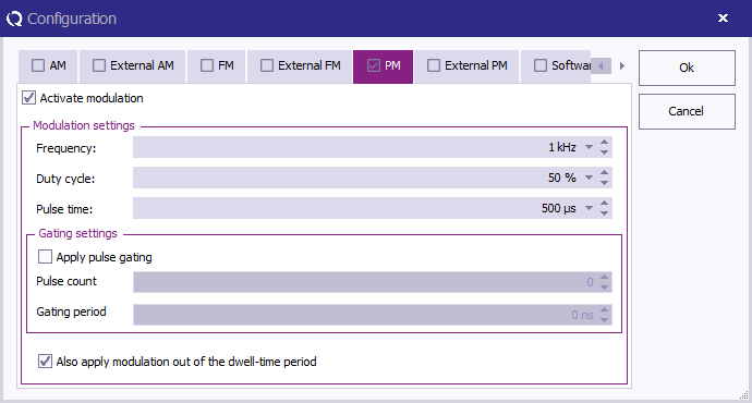
| Activate modulation
|
Check this checkbox to enable the pulse modulation.
|
| Frequency
|
The PM frequency 1 kHz.
|
| Duty Cycle
|
A duty cycle of 50%.
|
| Also apply modulation out of the dwell-time period
|
Check this checkbox to enable modulation outside the dwell-time.
|
At TestLevel click Add to add a new Test level and select TestLevel - Current substitution method
| Description
|
The description of the test level.
|
| Calibration file
|
Select the calibration file to use for this band.
|
| Test level
|
Variable current, and specify the correction file for the applicable test level.
|
| Calibration method
|
Select Forward Power.
|
| Tolerance
|
Specify the tolerance to use.
|
Next to the test level add a limit, At TestLevel click Add to add a new Limit and select Limit - Measured Current Limit
With this limit the level will not be regulated higher than the measured current in the cable even if the forward power is not reached yet.
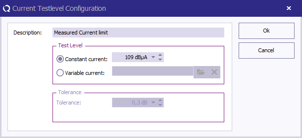
| Description
|
The description of the limit
|
| Constant current
|
The current to limit on.
|
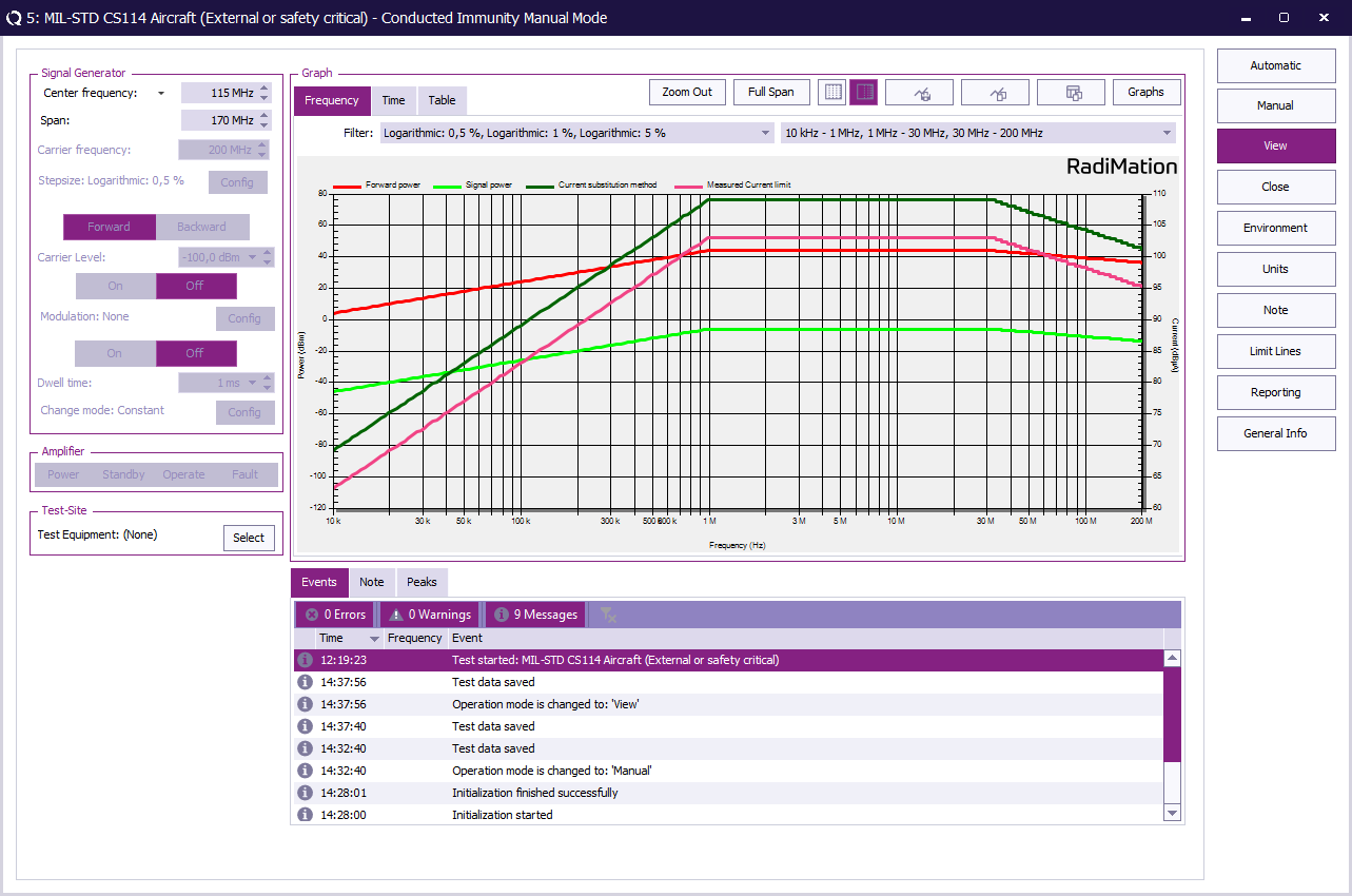
When all bands are configured press Start Test to run the EUT test.
EUT Test Result[edit]
Once the test is finished, the results of this test are stored in the EUT file and available as one of the performed Tests in the EUT file. Selecting the corresponding test result and pressing on Info will show the test results again.
Conclusion[edit]
The MIL-STD-461G CS114 calibration can be performed by using the Conducted immunity calibration.
The RadiMation® Conducted immunity multiband test can then be used to perform the MIL-STD-461G CS114 verification and the EUT test with a calibration file and the current sensor used as a limit in the EUT test.


