The Raditeq RSS2010B device driver is a Field Sensor which is supported by RadiMation®.
Configuration[edit]
The following tabs are available in the advanced configuration of the Raditeq RSS2010B:
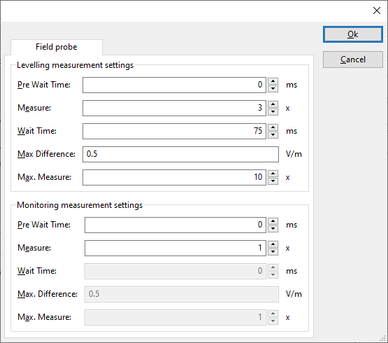
 Pre Wait Time Pre Wait Time
|
Wait time before starting the measurement-loop. Can be used to wait for a signal generator, and or amplifier to stabilize.
|
 Measure Measure
|
The minimum amount of measurements in the measure loop. Continues to loop even if field strength level is stable.
|
 Wait Time Wait Time
|
The wait time between each measurement is taken, during the measurement-loop.
|
 Max. Difference Max. Difference
|
If the measured field strength between each measurement in the measurement-loop, is less than this value. The measured field strength is stable. The measurement-loop will then stop.
|
 Max. Measure Max. Measure
|
The maximum amount of measure times, for the measurement-loop
|
According to these settings, RadiMation® will perform a minimum of 3 field strength measurements with a wait time between the measurements of 75ms. If all those 3 measurements are within 0.5 V/m, the field strength measurement is assumed to be stable, and RadiMation® will continue to average of the last 3 measurements. If the difference between the measurements is larger than the specified 0.5 V/m, an additional field strength measurement will be performed, and the last 3 samples will be compared to the 0.5 V/m difference again. At most 10 measurements will be performed if the difference between the 3 samples will not be within the specified 0.5 V/m.
Both for the leveling, and the monitoring these settings can be set individually.
The leveling is used, whenever RadiMation® is measuring the field strength, to regulate the signal generator.
If the field sensor is only used as input, without regulating on it, then the monitoring settings are used.
More detailed information on how to achieve a fast and stable field strength measurement are available in Application Note 106: Powermeter parameter configuration.
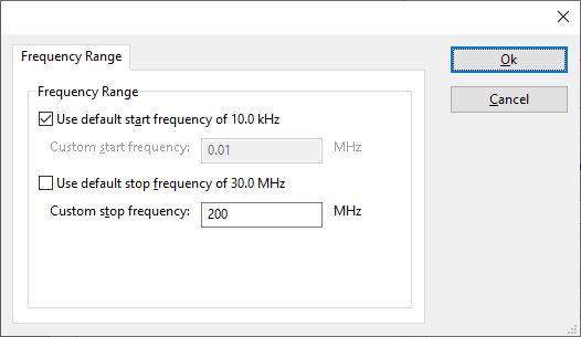
The frequency range of the Raditeq RSS2010B as provided by the manufacturer is shown and selected as default. It is possible to overrule these frequencies and to manually adjust the allowed frequency range of the Raditeq RSS2010B.
 Use default start frequency Use default start frequency
|
If the checkbox is checked, the default start frequency will be used as the lowest usable frequency in a test for this device.
|
 Custom start frequency Custom start frequency
|
If the Use default start frequency checkbox is unchecked, another start frequency (expressed in MHz) can be specified. The customized start frequency will then be used as the lowest usable frequency in a test for this device. The customized frequency can be a limitation or an extension of the default start frequency.
|
 Use default stop frequency Use default stop frequency
|
If the checkbox is checked, the default stop frequency will be used as the highest usable frequency in a test for this device.
|
 Custom stop frequency Custom stop frequency
|
If the Use default stop frequency checkbox is unchecked, another stop frequency (expressed in MHz) can be specified. The customized stop frequency will then be used as the highest usable frequency in a test for this device. The customized frequency can be a limitation or an extension of the default stop frequency.
|
Specifying a different frequency range can be useful if for example:
- A device (like a coupler, antenna, injection device, cable, etc...) is still usable (but out of specification) outside the standard suggested frequency range.
- An external mixer is used to measure an extended frequency range.
- An up- or down-convertor is used to shift the frequency range.
- A newer model of a device is present that has an extended frequency range, and still uses the same remote control commands.
Be careful changing these settings as RadiMation® is no longer able to verify if the Raditeq RSS2010B is used outside frequency range that is specified by the manufacturer. This may result in serious damage to your measurement device.
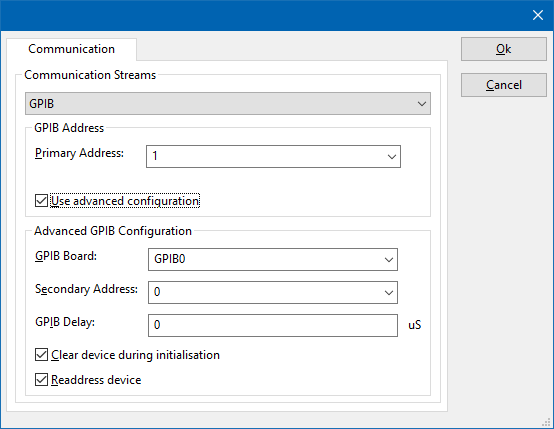
On the Communication tab, the desired communication method can be selected and configured. Depending on the selected method, additional relevant settings are shown and can be configured.
 Communication Streams Communication Streams
|
Selects the medium or method that should be used to communicate with the device. Depending on the capabilities of the device this can be one or more of:
Depending on the selected communication stream, additional configuration parameters can be configured. See the Communication Settings in Chapter 15, on how to configure each of these communication streams.
|
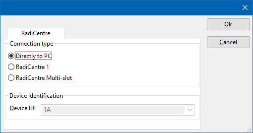
There are several methods in which the Raditeq RSS2010B can be connected to the PC. The Raditeq RSS2010B can for example be connected directly to the PC, or through a plugincard in a RadiCentre 1 or a multi-slot RadiCentre. More information on how to use the RadiCentre is present in the product manual of the RadiCentre. The settings on the RadiCentre tab can be used to specify how the Raditeq RSS2010B is connected.
When the Raditeq RSS2010B is connected to a multi-slot RadiCentre, also the slot number in which the plugincard is fitted, should be specified.
 Directly to PC Directly to PC
|
Specifies that the Raditeq RSS2010B is connected directly to the PC, without the use of a RadiCentre.
|
 RadiCentre 1 RadiCentre 1
|
Specifies that the Raditeq RSS2010B is connected to a plugincard that is fitted in a RadiCentre 1.
|
 RadiCentre multi-slot RadiCentre multi-slot
|
Specifies that the Raditeq RSS2010B is connected to a plugincard that is fitted in a multi-slot RadiCentre that also can be manually controlled using the display on the front of the RadiCentre. The slot number in which the plugin card is mounted can also be selected.
|
 RadiCentre multi-slot Ultra RadiCentre multi-slot Ultra
|
Specifies that the Raditeq RSS2010B is connected to a plugincard that is fitted in a multi-slot RadiCentre Ultra. This RadiCentre Ultra has no display, and can only be used when remote controlled.
|
The settings on this RadiCentre tab, only specifies if and which RadiCentre is used. The communication settings on the Communication tab specify the connection settings to communication with the measurement device.
The configuration on the Communication tab should be configured depending on the outgoing connection from the PC. Thus if Directly to PC is selected, the communication settings should be configured as what is actually used between the PC and the Raditeq RSS2010B itself. If RadiCentre 1, RadiCentre multi-slot or RadiCentre multi-slot Ultra is selected, the communication settings should be configured as what is actually used between the PC and the RadiCentre. In the configuration where a RadiPower is connected with USB to a multi-slot RadiCentre, which is connected by GPIB to the PC, the communication settings of the RadiPower device driver should thus be GPIB.
If the Raditeq RSS2010B is for example connected to slot 3 of a multi-slot RadiCentre which has IP address 192.168.178.95 and is connected by LAN to the PC, the following settings should be configured in the device driver of the Raditeq RSS2010B:
- RadiCentre tab
- Connection type: RadiCentre multi-slot, using as slot number: 3
- Communication tab
- Communication Stream: VISA
- LAN: 192.168.178.95
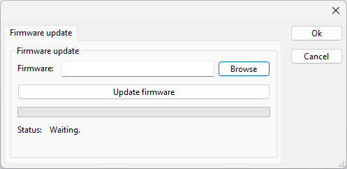
The Firmware update tab can be used to update the firmware of the Raditeq RSS2010B.
 Firmware Firmware
|
Specifies the filename of the firmware update file that should be used to update the firmware of the measurement device.
|
 Browse Browse
|
Allows to select the firmware update file.
|
 Update firmware Update firmware
|
Starts the actual firmware update. First some checks are performed, and if those checks are successful, the actual firmware update is performed.
|
 Status Status
|
Shows a message during the firmware update, indicating the performed action and the actual status.
|

|
Warning:
|
The firmware update can take a few minutes. During the actual firmware update the window is disabled, and cannot be closed. It is possible that Microsoft Windows shows messages that the RadiMation® software is not responding. Ignore those messages and do not kill, abort or end the software. Also do not disconnect the connection between the Raditeq RSS2010B and the PC, while the firmware update is being performed.
|
After the firmware update is completed, a messagebox will be shown that the firmware update has been completed successfully. In the case that an error has occurred, this will also be shown. In case that an error has been detected, it is strongly suggested to directly use the RadiMation® Error Report function to report the error to Raditeq.
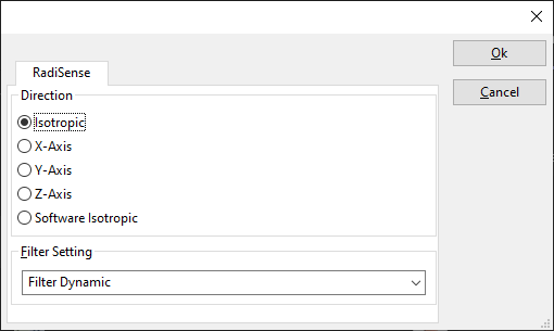
The RadiSense tab can be used to configure the specific settings of the Raditeq RSS2010B.
 Direction Direction
|
If the field strength of a specific single axis or an isotropic value should be measured.
|
 Filter Setting Filter Setting
|
The filter that should be used during the measurements.
|
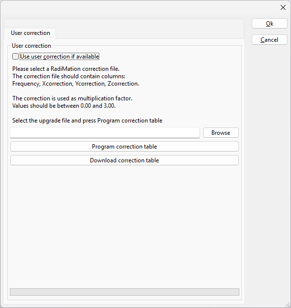
The User Correction tab can be used to upload the data of an user correction into the Raditeq RSS2010B. This correction data can be used by the probe internally to to correct the measured values.
 Use user correction if available Use user correction if available
|
If this option is activated, and if a user correction is stored in the probe, then the correction will be used by the probe itself, to internally correct the measured value with the user calibration data. If this option is off, no correction of the measured values will be done.
|
 Browse Browse
|
Allows to select the correction file that contains the user correction data of the Raditeq RSS2010B.
|
 Program correction table Program correction table
|
Starts the actual uploading of the correction table. First some checks are performed, and if those checks are successful, the actual uploading is performed.
|
 Download correction table Download correction table
|
Downloads the user correction table from the probe, if available. Then displays a 'Save As' prompt to save the table as a RadiMation correction file.
|


