RadiMation Application Note 156: Difference between revisions
No edit summary |
|||
| (5 intermediate revisions by 2 users not shown) | |||
| Line 1: | Line 1: | ||
__NOTOC__ | __NOTOC__ | ||
== How to perform a radiated emission substitution test == | == How to perform a radiated emission substitution test == | ||
This application note explains how to perform a radiated emission substitution test with {{RadiMation}}, as for example mentioned in [[ETSI | This application note explains how to perform a radiated emission substitution test with {{RadiMation}}, as for example mentioned in [[ETSI EN 300 328]] C5.3 and C5.4 | ||
The exact requirements and test methods are specified in the [[ETSI | The exact requirements and test methods are specified in the [[ETSI EN 300 328]]. | ||
== Necessary equipment == | == Necessary equipment == | ||
The following devices are necessary to perform a radiated emission substitution test: | The following devices are necessary to perform a radiated emission substitution test: | ||
* | * Signal generator | ||
* | * Transmitting Antenna | ||
* | * Receiving Antenna | ||
* | * Forward power meter | ||
* | * Coupler (0 dB coupling factor) | ||
== General remarks == | == General remarks == | ||
For higher quality and accuracy, it is still advised to use normal measurements practices like calibrating and zeroing the used powermeter. | |||
Cabling and system setup of all components from the receive antenna to the receiver that is used during Phase B, should be exactly the same during the normal emission measurements. Changes in cabling or antenna should result in a redetermination of the antenna correction. | |||
== Performing the measurements == | == Performing the measurements == | ||
| Line 65: | Line 64: | ||
==== Purpose ==== | ==== Purpose ==== | ||
Purpose of this phase is to measure the overall transfer from the transmit antenna to the receiver | Purpose of this phase is to measure the overall transfer from the transmit antenna to the receiver. | ||
==== Test set up ==== | ==== Test set up ==== | ||
| Line 100: | Line 99: | ||
==== Purpose ==== | ==== Purpose ==== | ||
Purpose of this phase is to use the measurement results obtained during '''phase A''' and '''B''' to determine the correction factor for the total system that can be used during an emission substitution measurement | Purpose of this phase is to use the measurement results obtained during '''phase A''' and '''B''' to determine the correction factor for the total system that can be used during an emission substitution measurement. | ||
This measurement measures the difference between the transmitted power and the received power at the receiving antenna. | |||
The chamber characteristics, which is the overall transfer factor of the chamber using the applicable measurement equipment, is represented by this difference. | |||
==== Calculations ==== | ==== Calculations ==== | ||
Latest revision as of 10:25, 9 September 2024
How to perform a radiated emission substitution test[edit]
This application note explains how to perform a radiated emission substitution test with RadiMation®, as for example mentioned in ETSI EN 300 328 C5.3 and C5.4
The exact requirements and test methods are specified in the ETSI EN 300 328.
Necessary equipment[edit]
The following devices are necessary to perform a radiated emission substitution test:
- Signal generator
- Transmitting Antenna
- Receiving Antenna
- Forward power meter
- Coupler (0 dB coupling factor)
General remarks[edit]
For higher quality and accuracy, it is still advised to use normal measurements practices like calibrating and zeroing the used powermeter.
Cabling and system setup of all components from the receive antenna to the receiver that is used during Phase B, should be exactly the same during the normal emission measurements. Changes in cabling or antenna should result in a redetermination of the antenna correction.
Performing the measurements[edit]
To perform the Radiated emission substitution measurements, the antenna correction factor of the test setup must first be determined.
This is done in three phases called (A, B & C).
Phase A: Determine the power being applied to the antenna[edit]
Purpose[edit]
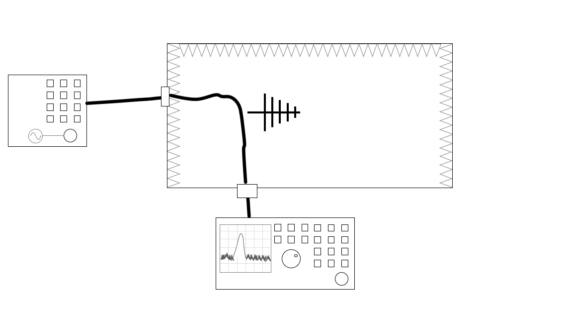
Purpose of this phase is to determine the power that is going into the transmit antenna during Phase B. Very often an attenuator is used between the signal generator and the antenna, to reduce mismatches. This phase is used to correct for cable, attenuator and signal generator losses.
Test set up[edit]
- A1. Build a setup with signal generator outside the chamber and the transmit antenna in the chamber.
- A2. Do not connect the transmit antenna yet, but connect the receiver on the location of the transmit antenna.
- A3. Sweep with a RI Fixed power test 0 dBm signal power over the frequency range. The antenna selected in the testsite of this test is not relevant. A coupler with a 0 dB coupling factor should also be used.
- A4. Also measure the forward power using the receiver. The power values measured as the forward power meter are the power values that are applied to the transmit antenna during phase C.
Test configuration[edit]
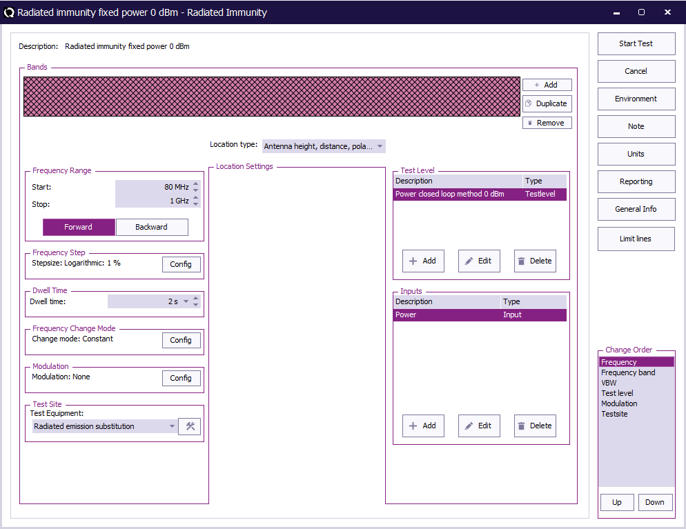
To perform the phase A test, create a radiated immunity multiband test. The radiated immunity multiband test, can be started by selecting from the menu:
-
 Tests
Tests
-
 Radiated Immunity
-
 Multiband
-
-
-
| The start frequency of the test. For example 1 GHz. |
| The stop frequency of the test. For example 6 GHz. |
| The frequency step. |
| The dwell time. |
| Constant. |
| The modulation |
| The equipment needed for the test. |
| Antenna height, distance, polarization, angle. |
| Specify the power closed loop method test level. |
| Specify the forward power measurement. |
Phase B: Determine the overall transfer of the measurement system[edit]
Purpose[edit]
Purpose of this phase is to measure the overall transfer from the transmit antenna to the receiver.
Test set up[edit]
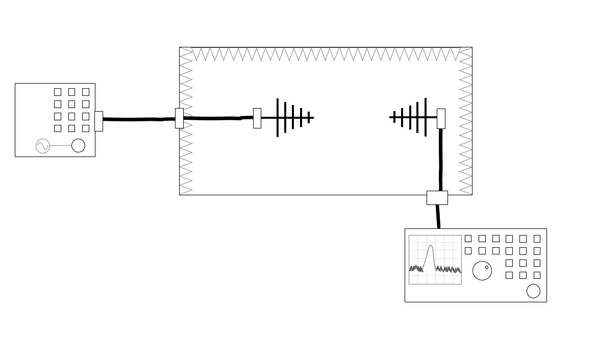
- B1. Build a setup with a signal generator outside the chamber and the transmit antenna in the chamber
- B2. Place the receiver outside the chamber and connect it to the receive antenna in the chamber
- B3. Sweep with a RI Fixed power test 0 dBm signal power over the frequency range. This can be the same test configuration as is used during step A3. The antenna selected in the test site of this test is not relevant. A coupler with a 0 dB coupling factor should also be used
- B4. Measure the forward power using the receiver. The power values measured as the forward power meter will be used to determine the correct correction factor
Test configuration[edit]
To perform the phase B test, create a radiated immunity multiband test. The radiated immunity multiband test, can be started by selecting from the menu:
-
 Tests
Tests
-
 Radiated Immunity
-
 Multiband
-
-
-
| The start frequency of the test. For example 1 GHz. |
| The stop frequency of the test. For example 6 GHz. |
| The frequency step. |
| The dwell time. |
| Constant. |
| The modulation |
| The equipment needed for the test. |
| Antenna height, distance, polarization, angle. |
| Specify the power closed loop method test level. |
| Specify the forward power measurement. |
Phase C: Calculate the correct antenna correction factor[edit]
Purpose[edit]
Purpose of this phase is to use the measurement results obtained during phase A and B to determine the correction factor for the total system that can be used during an emission substitution measurement. This measurement measures the difference between the transmitted power and the received power at the receiving antenna. The chamber characteristics, which is the overall transfer factor of the chamber using the applicable measurement equipment, is represented by this difference.
Calculations[edit]
For each frequency use the following calculation:
- : The antenna correction factor
- : The forward power during Phase A
- : the Transmit Antenna Factor of the transmit antenna compared to a dipole
- : The forward power during Phase B
The can be calculate from the calibrated Antenna Factor of the transmit antenna with:
- : The frequency, expressed in MHz
- The antenna factor of the antenna, expressed in dB/m
(The factor 2.15 is to correct from an isotropic antenna to a dipole antenna)
Application[edit]
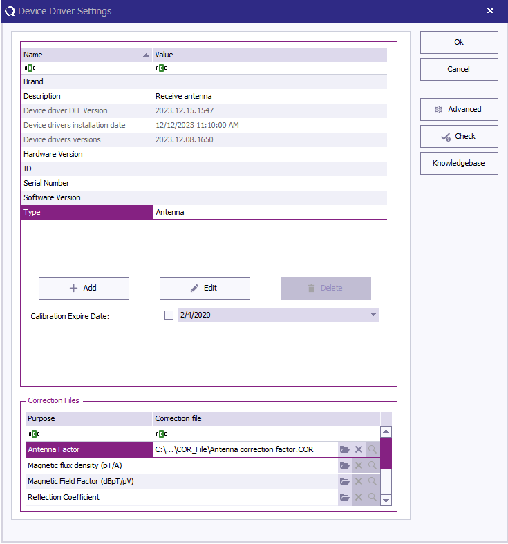
The calculated C can be used as the correction of the antenna during the real measurement, and can be placed in a correction file that is attached to the receiving antenna.
The EUT measurements[edit]
Purpose[edit]
Measuring the emission of the EUT using the antenna correction factors as determined in the previous phases.
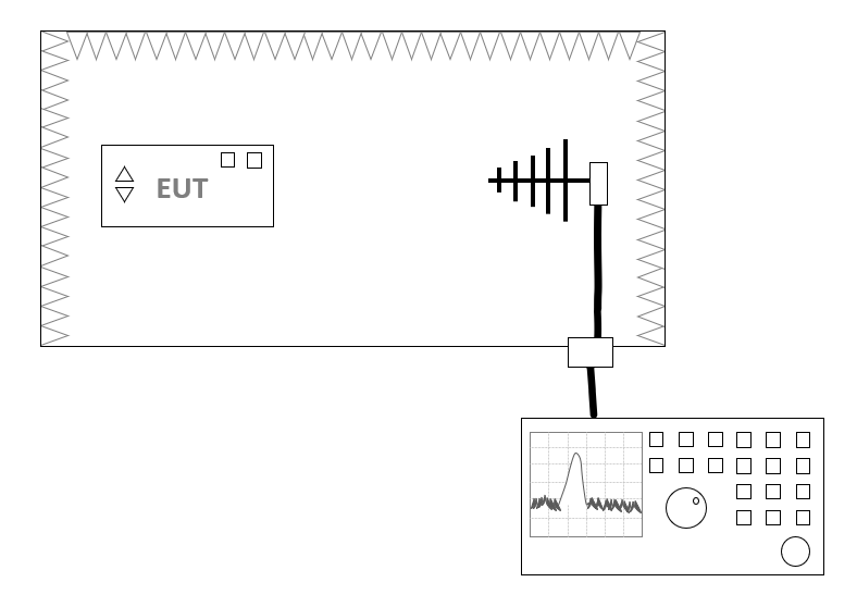
Test Set up[edit]
- On the location of the transmit antenna the EUT is positioned.
- The determined antenna correction factor (C) should be applied to the antenna that is used in the testsite during the measurement. No other corrections should be included in the testsite. Correction of the cables, preamplifiers and attenuators should not be done, because all these components were also present during phase B, and are thus already corrected for in the determined antenna correction factor (C).
Test configuration[edit]
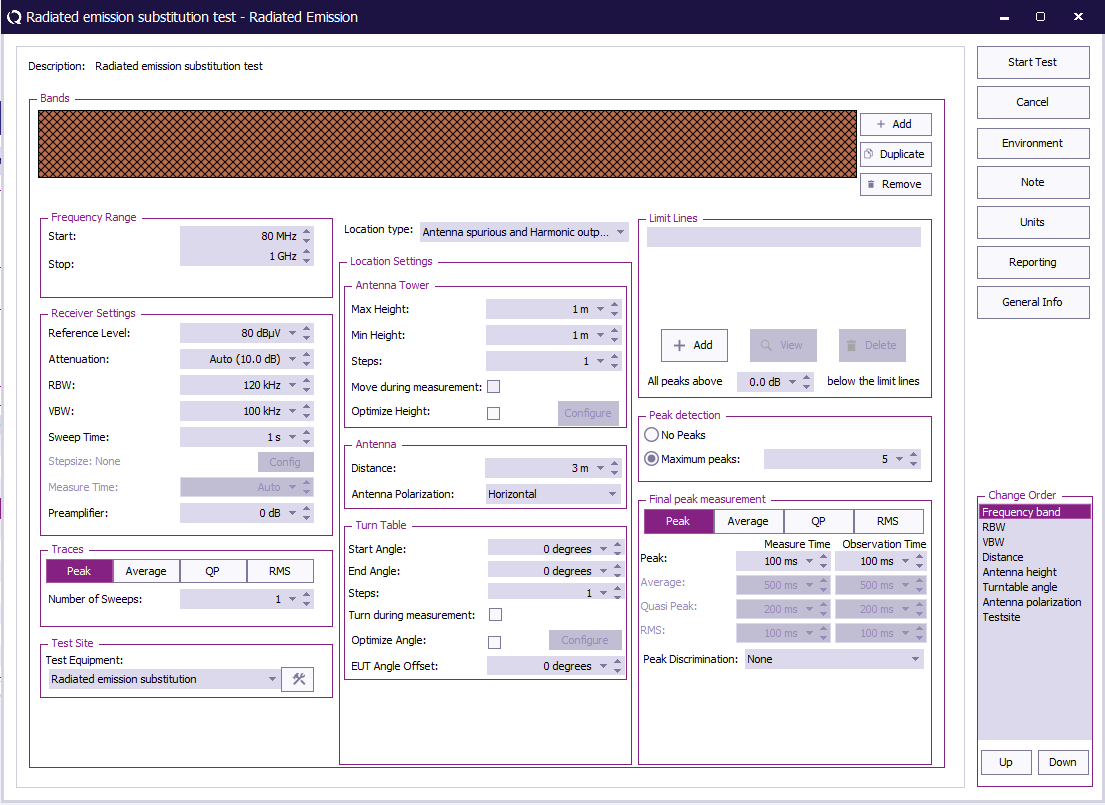
Perform a multi-band radiated emission measurement, with the 'Antenna Spurious and harmonics' location type. The values that are measured are the correct Effective radiated power measurements.
The radiated emission multi-band test, can be started by selecting from the menu:
-
 Tests
Tests
-
 Radiated emission
-
 Multiband
-
-
-
For more information regarding the radiated emission test configuration, please see: Radiated emission multiband test configuration
Conclusion[edit]
This application note outlines a three-phase process for determining the antenna correction factor in emission substitution measurements using RadiMation.
By systematically addressing power application to the antenna, measuring the overall transfer of the measurement system, and calculating the correct correction factor, users can achieve precise and reliable results.
The provided formulae and guidelines offer a methodology for calibrating the system, ensuring accurate measurements in real-world scenarios.
It is strongly adviced to adhere to the general remarks, maintaining consistency in setup and utilizing calibrated antenna factors.
This application note serves as a comprehensive guide, enabling users to perform these emission substitution measurements with confidence and accuracy.
