How to configure the RadiSwitch: Difference between revisions
No edit summary |
No edit summary |
||
| Line 11: | Line 11: | ||
{{ScreenElementDescription|Device ID| | {{ScreenElementDescription|Device ID| | ||
The switch matrix can be inserted in 1/2 or 8 channel system, in order to communicate with the correct card {{ | The switch matrix can be inserted in 1/2 or 8 channel system, in order to communicate with the correct card {{RadiMation}} has to know in which slot the card is inserted. | ||
}} | }} | ||
{{ScreenElementDescription|Communication|Select the communication media used to connect the PC to RadiCentre. | {{ScreenElementDescription|Communication|Select the communication media used to connect the PC to RadiCentre. | ||
}} | }} | ||
Latest revision as of 20:20, 5 October 2024
Configuring the RadiSwitch[edit]
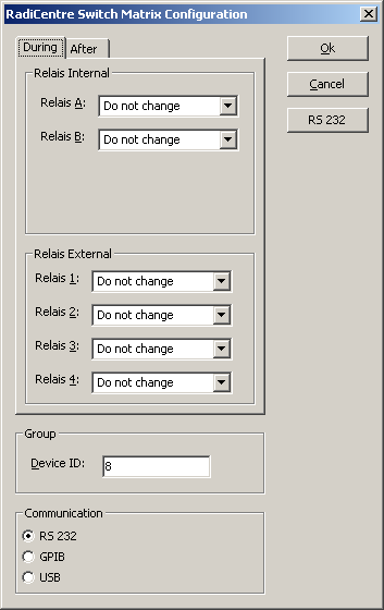
This tutorial is written for a 2 port switch but is the same for all the others.
|
There are two situation where it is possible to specify the switch configuration. These two situations are during and after the test. The setting during the test is send to the switch matrix just before the test is started. The setting after is send to the switch matrix after the test has ended. The idea behind it is that the setting during and after the test can be completely different. A possible situation is that the input of the analyser needs to be switch from the antenna, after the test has ended, to be sure that it is not blown up. Another possible scenario is that the high power amplifier is switched to a dummy load to be sure there is no RF power in the chamber. |
|
The settings for the internal an the external switches can be set separately. |
|
The switch matrix can be inserted in 1/2 or 8 channel system, in order to communicate with the correct card RadiMation® has to know in which slot the card is inserted. |
| Select the communication media used to connect the PC to RadiCentre. |
