Schneider Electric Modbus: Difference between revisions
No edit summary |
DevicesBot (talk | contribs) (Updated DeviceDriverInfo template) |
||
| (5 intermediate revisions by one other user not shown) | |||
| Line 4: | Line 4: | ||
|DeviceDriverName=MODBUS | |DeviceDriverName=MODBUS | ||
|DeviceType=Modbus | |DeviceType=Modbus | ||
|HideAutoData=1 | |||
|SupportedDeviceTypes=64 | |SupportedDeviceTypes=64 | ||
}} | }} | ||
The {{PAGENAME}} device driver can be configured to | The {{PAGENAME}} device driver can be configured to read specific registers from a [[wikipedia:Modbus|Modbus]] module, and present the values from those registers as EUT monitoring inputs in {{RadiMation}}. | ||
The following tabs are available in this device driver: | The following tabs are available in this device driver: | ||
| Line 20: | Line 20: | ||
On the {{ScreenElement|Modbus}} tab, the selection of the modbus module, and the communication protocol to access it can be selected. The following settings are available: | On the {{ScreenElement|Modbus}} tab, the selection of the modbus module, and the communication protocol to access it can be selected. The following settings are available: | ||
{{ScreenElementDescriptionStart}} | {{ScreenElementDescriptionStart}} | ||
{{ScreenElementDescription|Modbus address|The module address of the Modbus module from which the registers should be read.}} | {{ScreenElementDescription|Modbus address|The module address of the Modbus module from which the registers should be read. This address should be between 1 and 247.}} | ||
{{ScreenElementDescription|Modbus type|Selects the communication type to communicate with the modbus module. | {{ScreenElementDescription|Modbus type|Selects the communication type to communicate with the modbus module. Specific addressing like the COM-port or the TCP/IP-address must still be configured on the {{ScreenElement|Communication}} tab. {{ScreenElementDescriptionStart}} | ||
{{ScreenElementDescription|ASCII|Uses the text based communication over RS232 / RS485.}} | {{ScreenElementDescription|ASCII|Uses the text based communication over RS232 / RS485.}} | ||
{{ScreenElementDescription|RTU|Uses the binary communication protocol over RS232 / RS485.}} | {{ScreenElementDescription|RTU|Uses the binary communication protocol over RS232 / RS485.}} | ||
{{ScreenElementDescription|TCP|Uses ethernet communication based on TCP/IP.}} | {{ScreenElementDescription|TCP|Uses ethernet communication based on TCP/IP.}} | ||
{{ScreenElementDescriptionEnd}} | {{ScreenElementDescriptionEnd}} }} {{ScreenElementDescriptionEnd}} | ||
}} | |||
{{ScreenElementDescriptionEnd}} | |||
[[File:ModbusRegisterSettings.png]] | [[File:ModbusRegisterSettings.png]] | ||
On the {{ScreenElement|Settings}} tab, the configuration of the registers that should be read, can be configured. Depending on the specific Modbus module being communicated with, these settings should be configured to be matching with the registers available in that Modbus module. The following settings are available: | |||
{{ScreenElementDescriptionStart}} | |||
{{ScreenElementDescription|AD-Channel|The corresponding AD-Channel in {{RadiMation}} for which the configuration is set. Up to 40 channels (matching with 40 possible Modbus registers) can be configured.}} | |||
{{ScreenElementDescription|Function|The type of read function that is performed on the Modbus module. {{ScreenElementDescriptionStart}} | |||
{{ScreenElementDescription|Read Holding Register|The value of the holding register is read.}} | |||
{{ScreenElementDescription|Read Input Register|The value of the input register is read.}} | |||
{{ScreenElementDescriptionEnd}} }} | |||
{{ScreenElementDescription|Register|The number of the register that should be retrieved and read.}} | |||
{{ScreenElementDescription|Interpretation|The type of the data as it is read from the register, and how it should be represented in {{RadiMation}}. {{ScreenElementDescriptionStart}} | |||
{{ScreenElementDescription|Signed Int (16 bit)|The value is represented as a value between -32768 and 32767.}} | |||
{{ScreenElementDescription|Signed Int (32 bit)|The value is represented as a value between -2147483648 and 2147483647.}} | |||
{{ScreenElementDescription|Unsigned Int (16 bit)|The value is represented as a value between 0 and 65535.}} | |||
{{ScreenElementDescription|Unsigned Int (21 bit)|The value is represented as a value between 0 and 4294967295.}} | |||
{{ScreenElementDescription|Single Precision Floating Point (32 bit)|The value is represented as a 32 bit floating point number.}} | |||
{{ScreenElementDescriptionEnd}} }} | |||
{{ScreenElementDescriptionEnd}} | |||
Latest revision as of 02:06, 19 February 2025
The Schneider Electric Modbus device driver is a AD Converter which is supported by RadiMation®.
The Schneider Electric Modbus device driver can be configured to read specific registers from a Modbus module, and present the values from those registers as EUT monitoring inputs in RadiMation®.
The following tabs are available in this device driver:
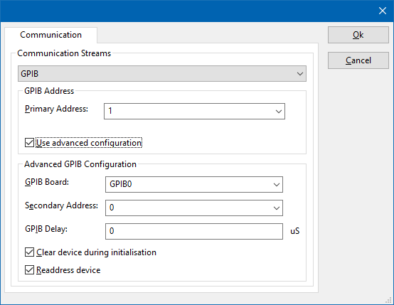
On the Communication tab, the desired communication method can be selected and configured. Depending on the selected method, additional relevant settings are shown and can be configured.
| Selects the medium or method that should be used to communicate with the device. Depending on the capabilities of the device this can be one or more of:
Depending on the selected communication stream, additional configuration parameters can be configured. See the Communication Settings in Chapter 15, on how to configure each of these communication streams. |
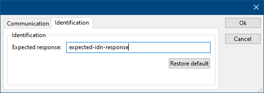
On the Identification tab, the expected *IDN? response of the test and measurement device can be configured. It is used to determine if the correct test and measurement device is connected.
| The expected *IDN? response of a device. It can be changed in the case the commands are the same for another device for which no RadiMation® driver is available yet. |
| Restores the original Exepected response. |
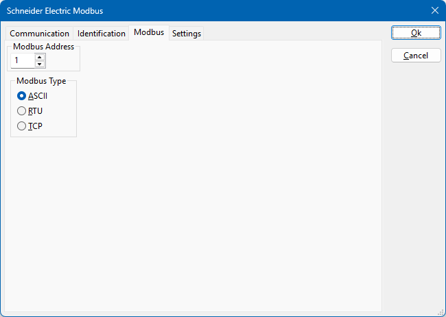
On the Modbus tab, the selection of the modbus module, and the communication protocol to access it can be selected. The following settings are available:
| The module address of the Modbus module from which the registers should be read. This address should be between 1 and 247. |
Selects the communication type to communicate with the modbus module. Specific addressing like the COM-port or the TCP/IP-address must still be configured on the Communication tab.
|
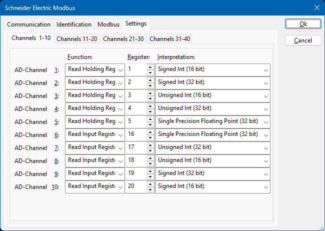
On the Settings tab, the configuration of the registers that should be read, can be configured. Depending on the specific Modbus module being communicated with, these settings should be configured to be matching with the registers available in that Modbus module. The following settings are available:
| The corresponding AD-Channel in RadiMation® for which the configuration is set. Up to 40 channels (matching with 40 possible Modbus registers) can be configured. |
The type of read function that is performed on the Modbus module.
|
| The number of the register that should be retrieved and read. |
The type of the data as it is read from the register, and how it should be represented in RadiMation®.
|


