Signal Offset With Receiver: Difference between revisions
Jump to navigation
Jump to search
No edit summary |
No edit summary |
||
| Line 27: | Line 27: | ||
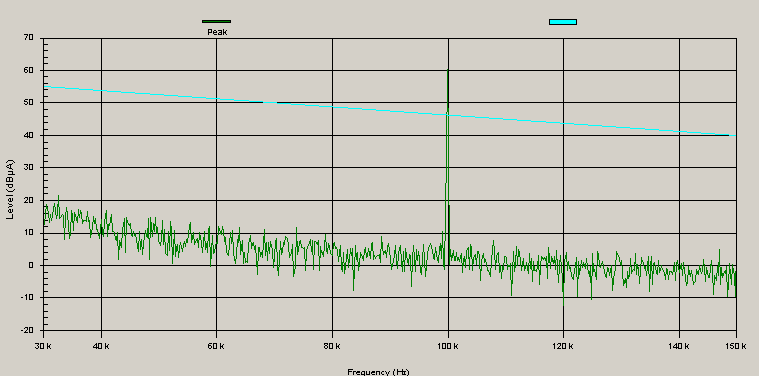
As you can see the emission is starting a little bit before the 100 kHz. | As you can see the emission is starting a little bit before the 100 kHz. | ||
Marconi 2024 Reference connector | |||
[[Image:Marconi Ref Connector.JPG]] | |||
R & S Esi 40 Reference connector | |||
[[Image:ESI Ref Connector.JPG]] | |||
Revision as of 12:13, 20 December 2007
this document is describing a possible solution for the frequency offset of the signal generator and the receiver.
| Receiver Settings | |
|---|---|
| RBW | 200 Hz |
| Step size | 200 Hz |
Note: The step frequency of 200 Hz is taken increase the impact, to get the right frequency use RBW/2 or less as step frequency.
| Signal Generator Settings | |
|---|---|
| Carrier Frequency | 100 kHz |
With these settings we get the following emission spectrum:

As you can see the emission is starting a little bit before the 100 kHz.
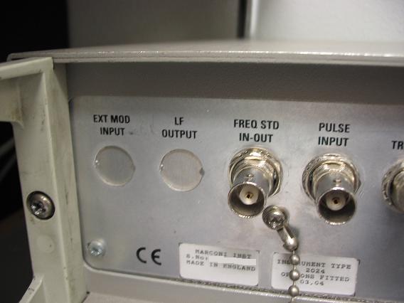
Marconi 2024 Reference connector
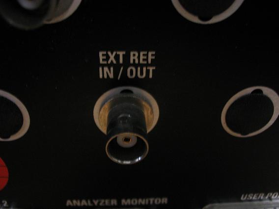
R & S Esi 40 Reference connector

