RadiMation Application Note 106: Difference between revisions
No edit summary |
No edit summary |
||
| (5 intermediate revisions by the same user not shown) | |||
| Line 1: | Line 1: | ||
= Powermeter parameter configuration = | = Powermeter parameter configuration = | ||
This application note describes how the measurement parameters of a Powermeter can be configured to get a fast and stable power measurement. | This application note describes how the measurement parameters of a Powermeter can be configured to get a fast and stable power measurement. Even though this aplication note explains the possible configuration of the powermeter, all these settings can also be configured and are applicable for a field strength sensor. | ||
Each powermeter in [[RadiMation|{{RadiMation}}]] has a | Each powermeter in [[RadiMation|{{RadiMation}}]] has a {{ScreenElement|Powermeter}} configuration tab in the advanced configuration of the device driver. | ||
In this tab, the accuracy of power measurement can be optimized. | In this tab, the accuracy of power measurement can be optimized. | ||
This function allows to make multiple measurements, and wait until the value is stable | This function allows to make multiple measurements, and wait until the value is stable, using a measurement-loop. | ||
[[File:PowerMeterPanel.png]] | [[File:PowerMeterPanel.png]] | ||
| Line 16: | Line 16: | ||
{{ScreenElementDescriptionEnd}} | {{ScreenElementDescriptionEnd}} | ||
These settings can be set for a levelling and monitoring measurement individually. | |||
The leveling measurement is used, whenever RadiMation is measuring the power, to regulate the signal generator. | |||
For example, if you have a immunity power closed loop method. This will regulate the signal generator until certain power is measured. In this case, the leveling measurement settings are used. | |||
If the powermeter is only used as input, without regulating on it, then the monitoring measurement settings are used. This is for example used when a power measurement is included in the inputs list of an immunity test. | |||
If the | According to values shown in the above screenshot, {{RadiMation}} will perform a minimum of 3 power measurements with a wait time between the measurements of 75ms. If all those 3 measurements are within 0.1 dB, the power measurement is assumed to be stable, and {{RadiMation}} will continue to use the average of those 3 measurements. If the difference between the measurements is larger than the specified 0.1 dB, an additional power measurement will be performed, and the last 3 samples will be compared to the 0.1 dB difference again. At most 10 measurements will be performed if the difference between the 3 samples will not be within the specified 0.1 dB. | ||
This could result in 4 different situations: | |||
# '''Once the first {{ScreenElement|Measure}} amount samples are measured.'''<BR />If the results of the first 3 measurements are within the {{ScreenElement|Max. Difference}} of 0.1 dB, then the averaged measurement value (of those 3 measurements) is used. | |||
# '''If more measurements are needed.'''<BR />If the results of the first 3 measurements are performed and the results are not within the {{ScreenElement|Max. Difference}} of 0.1 dB, then one new additional measurement is performed and {{RadiMation}} will use the last 3 measurements (thus, the very first measurement will be neglected) to determine if the results are now within the {{ScreenElement|Max. Difference}} of 0.1 dB. This process will repeat until the 3rd or 4th situation is reached. | |||
# '''When after new measurements the difference is within 0.1 dB.'''<BR />If after the additional measurements, the difference between the last 3 measurements is within the {{ScreenElement|Max. Difference}} of 0.1 dB, the average of the last 3 measurements is used. | |||
# '''After in total 10 measurements are performed.'''<BR />If in total 10 measurements (which was specified for the {{ScreenElement|Max. Measure}}) are performed, and the difference between those samples is still larger than the specified {{ScreenElement|Max. Difference}} of 0.1 dB, the average of the last 3 performed measurements is used. | |||
The leveling settings (for regulating the signal generator) should in general be set to measure more accurately, with multiple measurement samples, because it has direct influence on the accuracy of the regulated testlevel. Another reason to use multiple measurement samples in the levelling settings, is that those measurements are performed shortly after the carrier level of the signal generator is changed, and the generated power could still be fluctuating and instable. | The leveling settings (for regulating the signal generator) should in general be set to measure more accurately, with multiple measurement samples, because it has direct influence on the accuracy of the regulated testlevel. Another reason to use multiple measurement samples in the levelling settings, is that those measurements are performed shortly after the carrier level of the signal generator is changed, and the generated power could still be fluctuating and instable. | ||
| Line 49: | Line 54: | ||
* If during a leveling, the carrier going up and down a lot. Then the measure-loop is going to fast, and should be slowed down. | * If during a leveling, the carrier going up and down a lot. Then the measure-loop is going to fast, and should be slowed down. | ||
* If measurement is slow, you can reduce the delays between measurement, or allow a lesser stable output. Make sure (see first point) its not too fast. | * If measurement is slow, you can reduce the delays between measurement, or allow a lesser stable output. Make sure (see first point) its not too fast. | ||
Latest revision as of 10:42, 8 March 2021
Powermeter parameter configuration[edit]
This application note describes how the measurement parameters of a Powermeter can be configured to get a fast and stable power measurement. Even though this aplication note explains the possible configuration of the powermeter, all these settings can also be configured and are applicable for a field strength sensor.
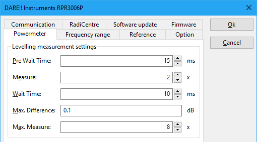
Each powermeter in RadiMation® has a Powermeter configuration tab in the advanced configuration of the device driver. In this tab, the accuracy of power measurement can be optimized. This function allows to make multiple measurements, and wait until the value is stable, using a measurement-loop.
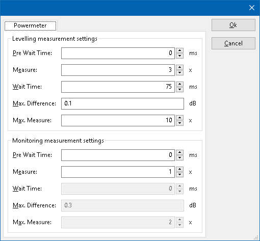
| Wait time before starting the measurement-loop. Can be used to wait for a signal generator, and or amplifier to stabilize. |
| The minimum amount of measurements in the measure loop. Continues to loop even if power level is stable. |
| The wait time before each measurement is taken, during the measurement-loop. |
| If the measured power between each measurement in the measurement-loop, is less than this value. The measured power is stable. The loop will stop. |
| The maximum amount of measure times, for the measurement-loop |
These settings can be set for a levelling and monitoring measurement individually.
The leveling measurement is used, whenever RadiMation is measuring the power, to regulate the signal generator.
For example, if you have a immunity power closed loop method. This will regulate the signal generator until certain power is measured. In this case, the leveling measurement settings are used.
If the powermeter is only used as input, without regulating on it, then the monitoring measurement settings are used. This is for example used when a power measurement is included in the inputs list of an immunity test.
According to values shown in the above screenshot, RadiMation® will perform a minimum of 3 power measurements with a wait time between the measurements of 75ms. If all those 3 measurements are within 0.1 dB, the power measurement is assumed to be stable, and RadiMation® will continue to use the average of those 3 measurements. If the difference between the measurements is larger than the specified 0.1 dB, an additional power measurement will be performed, and the last 3 samples will be compared to the 0.1 dB difference again. At most 10 measurements will be performed if the difference between the 3 samples will not be within the specified 0.1 dB.
This could result in 4 different situations:
- Once the first Measure amount samples are measured.
If the results of the first 3 measurements are within the Max. Difference of 0.1 dB, then the averaged measurement value (of those 3 measurements) is used. - If more measurements are needed.
If the results of the first 3 measurements are performed and the results are not within the Max. Difference of 0.1 dB, then one new additional measurement is performed and RadiMation® will use the last 3 measurements (thus, the very first measurement will be neglected) to determine if the results are now within the Max. Difference of 0.1 dB. This process will repeat until the 3rd or 4th situation is reached. - When after new measurements the difference is within 0.1 dB.
If after the additional measurements, the difference between the last 3 measurements is within the Max. Difference of 0.1 dB, the average of the last 3 measurements is used. - After in total 10 measurements are performed.
If in total 10 measurements (which was specified for the Max. Measure) are performed, and the difference between those samples is still larger than the specified Max. Difference of 0.1 dB, the average of the last 3 performed measurements is used.
The leveling settings (for regulating the signal generator) should in general be set to measure more accurately, with multiple measurement samples, because it has direct influence on the accuracy of the regulated testlevel. Another reason to use multiple measurement samples in the levelling settings, is that those measurements are performed shortly after the carrier level of the signal generator is changed, and the generated power could still be fluctuating and instable.
The monitoring settings on the other hand, can be in general set to a faster measurement, as it is only used for an indication of the measured power. Also the inputs are measured after the levelling of the testlevel is completed, and this thus happens after a longer time after the carrier level of the signal generator has changed. The generated power is thus not changing and fluctuating anymore, and is assumed to be more stable.
Example[edit]
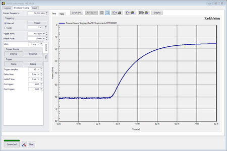
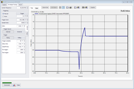
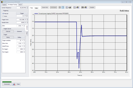
See the measured power graphs above. From left to right: Turning carrier on, change carrier up from -30 to -10, change carrier down from -10 to -20 dBm. We will use this information to determine the powermeter settings. The graphs are related to the output level of the signal generator, therefor we set the Leveling measurement settings.
| From the 3 graphs, it takes at least 15 ms before any of the output levels is stable. We therefor set the value of 15 ms as pre wait time. |
| We measure 2 times. We check 2 measurements to be within the stable tolerance. |
| In the graphs, it can take up to 30+15 ms before the output level is stabilized. To be safe, we will use 80ms maximum time to stabilize the output level. See Max Measure times: We should measure 8 times maximum. We then divide this 80 milliseconds over 8 times. Which means 10 milliseconds wait time per measurement. |
| When the output level is stable, the power is very less fluctuating. We could set the "Max difference" to 0.1 dB. |
| We should measure a maximum of 80ms. We take 10ms for each measurement. We should therefor measure 8 times maximum. |
- If during a leveling, the carrier going up and down a lot. Then the measure-loop is going to fast, and should be slowed down.
- If measurement is slow, you can reduce the delays between measurement, or allow a lesser stable output. Make sure (see first point) its not too fast.
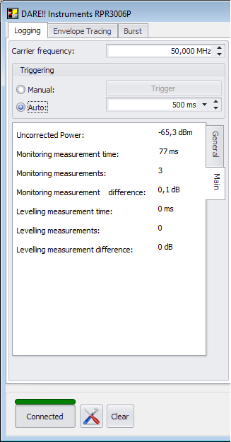
Once the settings have been configured, you may test these settings using the RadiMation free powermeter window.
In the logging tab, and Main sub tab, testing output can be found. Here you will find the actual required measure times, time, and allowed difference.
| Warning: | With the available settings, you can make measurements very slow. In some cases, you can end up in measuring noise. Then the maximum measure times will be used, since the power level in noise, is not stable. You may need to decrease the Max. Measure value in that case. |
