RadiMation Application Note 123: Difference between revisions
(Created page with " RadiMation Application Note 123 Jump to:navigation, search Implementing Switch Matrix design in RadiMation®[edit] This application note describes how to implement a switch...") |
No edit summary |
||
| (18 intermediate revisions by 2 users not shown) | |||
| Line 1: | Line 1: | ||
= Implementing the control of a switch matrix in {{RadiMation}} = | |||
This application note describes how to implement a switch matrix design into [[RadiMation|{{RadiMation}}]] | |||
RadiMation | When making a test setup it can be needed to switch to different equipment for different settings or frequency ranges. This is supported in [[RadiMation|{{RadiMation}}]] by being able to make a specific driver for a switch matrix to be used in a specific test-site. Later in this text this will hopefully become more clear. | ||
A switch matrix design is normally a drawing or something like a excel sheet. It will tell you what is connected when the relays are in a certain state. The relays normally can be in two modes, being: 'Normally open' and 'Normally closed'. | |||
* 'Normally closed' indicates the state of the relais when it is completely unpowered, and thus is the state in which it returns when it is being disconnected. | |||
* 'Normally open' indicates the connection that is made when which is opened (not connected) when the relais is completely unpowered. To make a connection on the 'Normally open' state, the relais has to be actively controlled. Based on these state, and the switch matrix design we know the flow of the signals and which switches need to be set to create the desired signal path. | |||
== How to use the switch matrix == | |||
To use a switch matrix you need to add them with the needed settings to the test site. | |||
Below we will explain an example use-case scenario. We have chosen to show how to implement a specific scenario instead of explaining all the different steps in the process. This is because it is very case specific how you would set it up. By explaining a scenario you get an idea why it is set-up in a specific way. | |||
The scenario that we use an example: | |||
You have a RI test that you need to set up. The path and devices needed in the different bands need to be different, also we want to use the same measurement equipment for both paths. This means that you need to make two test sites. | |||
One for the low range and one for the high range. In this way you can select the right test-site for the frequency range you are working on. If the test-site is properly set up it will automatically set all the relays need to create the path requested. | |||
If the | |||
We have two ranges with the following equipment: | |||
# Radiated Immunity - 80 MHz - 1 GHz: | |||
#* AMP 200w: 80 MHz - 1 GHz | |||
#* Coupler: 80 MHz - 1 GHz | |||
#* Antenna: 80 MHz - 1 Ghz | |||
# Radiated Immunity - 1 GHz - 3 GHz | |||
#* AMP 25w: 1 GHz - 3.0 GHz | |||
#* Coupler: 1 GHz - 3.2 GHz | |||
#* Antenna: 1 GHz - 4.2 Ghz | |||
Apart from this equipment we also have two power meters to measure our forward and reflected power. Now that we know all the parameters we can start to specify our design. | |||
We need two signal paths but want be able to measure both with the same power meter. | |||
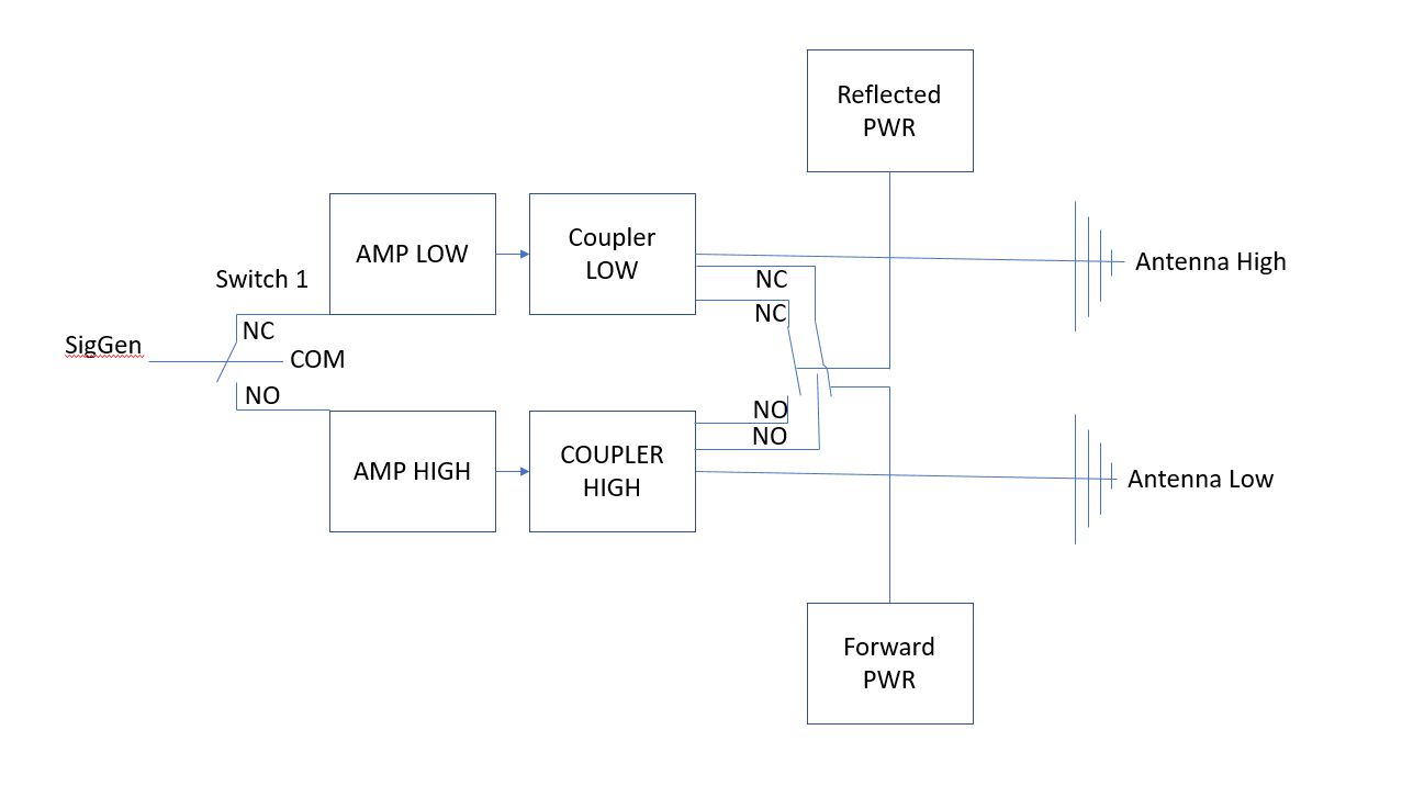
See the picture below for a schematic overview how this could be set up. | |||
[[File:Switches.png]] | |||
Now we have our design we can start to translate the design back to Radimation and start to configure the different components. In this specific case we will use separate switches. It is also possible to use switchboards that have more then one relay. | |||
== Configuring and using switches in RadiMation == | |||
Now that you have thought out your design we can configure RadiMation. | |||
=== Configuring the switch === | |||
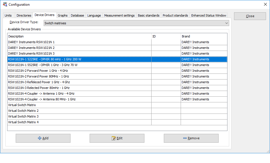
First start with adding the switches and configure them correctly. Below you will see a picture of the device driver switch matrix: | |||
This | [[File:SwitchMatrix.png]] | ||
We will show one example in detail. For the other switches, the process is the same. For explaining purposes I will use the switch design shown in the schematic drawing. | |||
If we look at the first device in the switch design we see that we need to be able to switch between the two amps available in the system. We want to use the amplifier suitable for low frequency for the tests from 80 MHz - 1 GHz (AMP1). For the range 1 GHz to 3 GHz we need to switch to the amplifier for the higher range 1.0 GHz - 3.0 Ghz (AMP2). | |||
Looking at our switch-design we see that AMP1 is Connected to the normally closed output of the switch. Amp2 is connected to the normally open output of the switch. Now we have the data we need to set the drivers up correctly. | |||
First make two drivers for the switch settings for AMP1 and AMP2. | |||
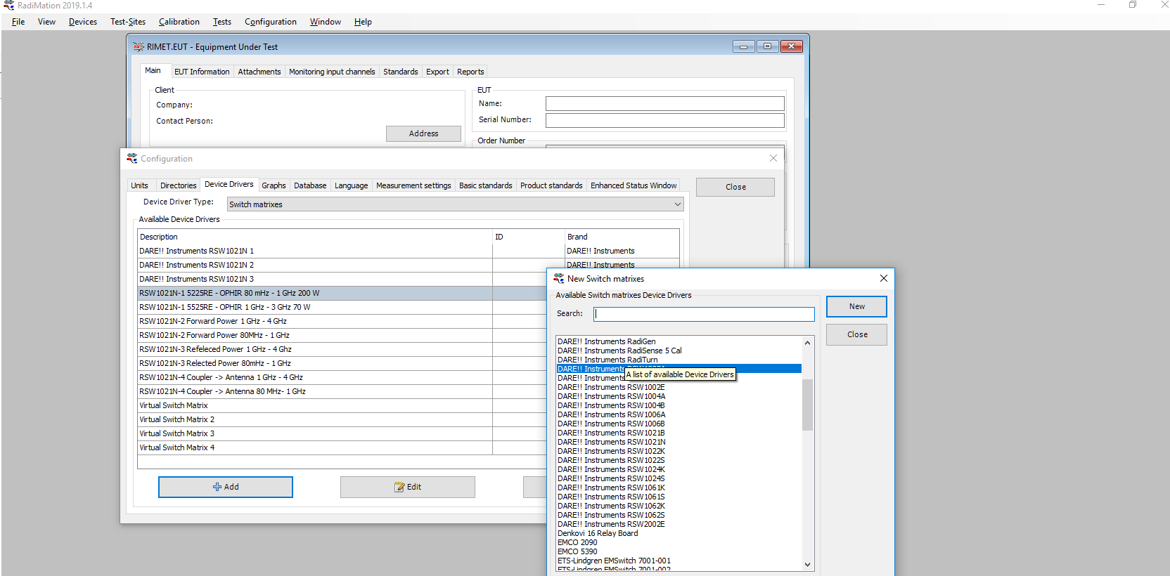
Go to device drivers and click {{ScreenElement|Add}}. | |||
[[File:AddDriver2.png]] | |||
Change the description to a name that reflects the connection. | |||
[[File:SwitchAmp1.png]] | |||
Do not configure it yet, but make a second switch matrix for AMP2. | |||
[[File:SwitchAmp2.png]] | |||
Now we know that we have made the drivers for our two settings of the switch we can configure it. | |||
Go to device drivers and open the switch we just created for AMP1. Go to {{ScreenElement|Advanced}}. | |||
[[File:Communicationswitch.png]] | |||
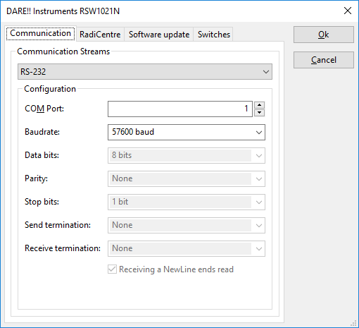
Select the correct protocol and configure it. Now go to the tab {{ScreenElement|Switches}}. | |||
[[File:Communicationswitch2.png]] | |||
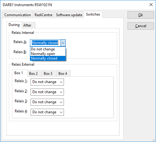
We are now configuring the switch for AMP1. When we look at our switch design we see that we need the switch to be in {{ScreenElement|Normally Closed}}. As the switch I have used in this example only has on relay we set Relais A to {{ScreenElement|Normally Closed}}. | |||
Following this steps you have now made a driver that can be used to switch the signal of the system to the input of AMP1. To finish our example we have to do the same for AMP2. | |||
Go to {{ScreenElement|Device drivers}}, select Switch matrixes and select the switch matrix that we have created for AMP2. Open the driver and go to {{ScreenElement|advanced}}. | |||
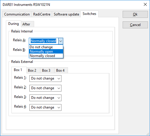
Set the communication on the {{ScreenElement|communication}} tab. This will be the same as the previous driver as we are communicating to the same device. We only want it to switch the relay to {{ScreenElement|Normally open}}. Make sure that you set this on the {{ScreenElement|Switches}} tab. | |||
[[File:Communicationswitch3.png]] | |||
=== Using the switch in your test-site configuration=== | |||
Now that we have made the drivers, named and configured them we are ready to implement them in our test system. For now I will stick with example used above. In this case two test sites will work well to set the path correctly for the low and high range. | |||
Go to {{ScreenElement|Test-sites}}, and click on {{ScreenElement|Add}} to make a new test-site, also providing it with a logical name like for example: "Radiated Immunity - 80MHz - 1GHz" | |||
Now add all the devices needed to perform the test. In this case that would be the amplifier, signal generator, power meters and an antenna. To make sure that the switching is done correctly we need to add the drivers for the switch matrixes. | |||
If we look at the switch matrix design we know that we need to set the signal generator signal to the right amplifier and make sure that the powermeters are using the signal of the right coupler. | |||
In the case of this example this means that I need to add three switches. If a switch matrix has more relays, one switch would have been enough as you can set all the relays from the same driver. | |||
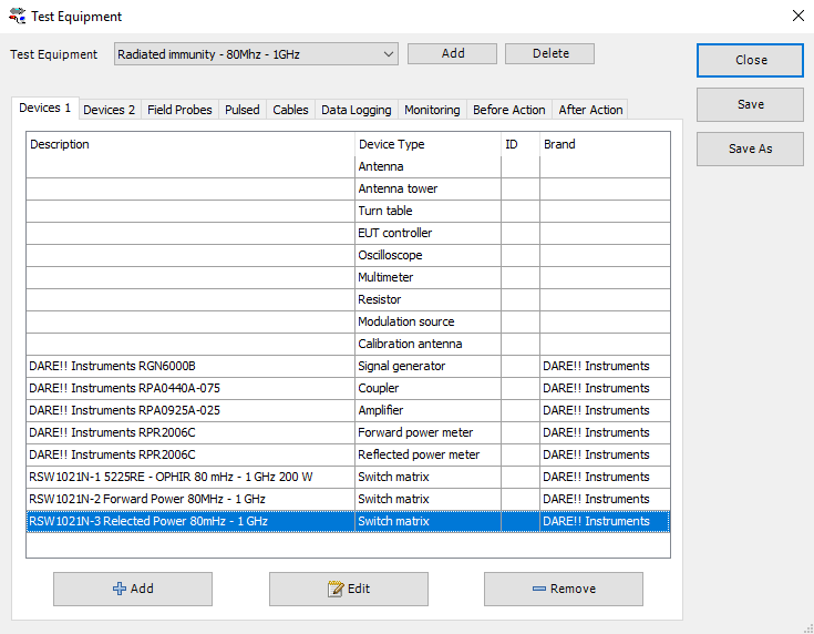
Below you see the picture of the test site made for the low-end path. | |||
[[File:TestsiteLow.png]] | |||
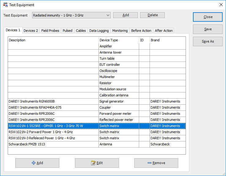
Below we have done the same except that it was for the high path. You can see that it resembles each other however the switches are set correctly for the range by selecting the correct test site. | |||
[[File:TestsiteHigh.png]] | |||
[[Category:RadiMation Application Note]] | |||
[[Category:RadiMation]] | |||
Latest revision as of 19:18, 28 January 2022
Implementing the control of a switch matrix in RadiMation®[edit]
This application note describes how to implement a switch matrix design into RadiMation®
When making a test setup it can be needed to switch to different equipment for different settings or frequency ranges. This is supported in RadiMation® by being able to make a specific driver for a switch matrix to be used in a specific test-site. Later in this text this will hopefully become more clear.
A switch matrix design is normally a drawing or something like a excel sheet. It will tell you what is connected when the relays are in a certain state. The relays normally can be in two modes, being: 'Normally open' and 'Normally closed'.
- 'Normally closed' indicates the state of the relais when it is completely unpowered, and thus is the state in which it returns when it is being disconnected.
- 'Normally open' indicates the connection that is made when which is opened (not connected) when the relais is completely unpowered. To make a connection on the 'Normally open' state, the relais has to be actively controlled. Based on these state, and the switch matrix design we know the flow of the signals and which switches need to be set to create the desired signal path.
How to use the switch matrix[edit]
To use a switch matrix you need to add them with the needed settings to the test site.
Below we will explain an example use-case scenario. We have chosen to show how to implement a specific scenario instead of explaining all the different steps in the process. This is because it is very case specific how you would set it up. By explaining a scenario you get an idea why it is set-up in a specific way.
The scenario that we use an example: You have a RI test that you need to set up. The path and devices needed in the different bands need to be different, also we want to use the same measurement equipment for both paths. This means that you need to make two test sites.
One for the low range and one for the high range. In this way you can select the right test-site for the frequency range you are working on. If the test-site is properly set up it will automatically set all the relays need to create the path requested.
We have two ranges with the following equipment:
- Radiated Immunity - 80 MHz - 1 GHz:
- AMP 200w: 80 MHz - 1 GHz
- Coupler: 80 MHz - 1 GHz
- Antenna: 80 MHz - 1 Ghz
- Radiated Immunity - 1 GHz - 3 GHz
- AMP 25w: 1 GHz - 3.0 GHz
- Coupler: 1 GHz - 3.2 GHz
- Antenna: 1 GHz - 4.2 Ghz
Apart from this equipment we also have two power meters to measure our forward and reflected power. Now that we know all the parameters we can start to specify our design.
We need two signal paths but want be able to measure both with the same power meter.
See the picture below for a schematic overview how this could be set up.
Now we have our design we can start to translate the design back to Radimation and start to configure the different components. In this specific case we will use separate switches. It is also possible to use switchboards that have more then one relay.
Configuring and using switches in RadiMation[edit]
Now that you have thought out your design we can configure RadiMation.
Configuring the switch[edit]
First start with adding the switches and configure them correctly. Below you will see a picture of the device driver switch matrix:
We will show one example in detail. For the other switches, the process is the same. For explaining purposes I will use the switch design shown in the schematic drawing.
If we look at the first device in the switch design we see that we need to be able to switch between the two amps available in the system. We want to use the amplifier suitable for low frequency for the tests from 80 MHz - 1 GHz (AMP1). For the range 1 GHz to 3 GHz we need to switch to the amplifier for the higher range 1.0 GHz - 3.0 Ghz (AMP2).
Looking at our switch-design we see that AMP1 is Connected to the normally closed output of the switch. Amp2 is connected to the normally open output of the switch. Now we have the data we need to set the drivers up correctly.
First make two drivers for the switch settings for AMP1 and AMP2.
Go to device drivers and click Add.
Change the description to a name that reflects the connection.
Do not configure it yet, but make a second switch matrix for AMP2.
Now we know that we have made the drivers for our two settings of the switch we can configure it.
Go to device drivers and open the switch we just created for AMP1. Go to Advanced.
Select the correct protocol and configure it. Now go to the tab Switches.
We are now configuring the switch for AMP1. When we look at our switch design we see that we need the switch to be in Normally Closed. As the switch I have used in this example only has on relay we set Relais A to Normally Closed.
Following this steps you have now made a driver that can be used to switch the signal of the system to the input of AMP1. To finish our example we have to do the same for AMP2.
Go to Device drivers, select Switch matrixes and select the switch matrix that we have created for AMP2. Open the driver and go to advanced.
Set the communication on the communication tab. This will be the same as the previous driver as we are communicating to the same device. We only want it to switch the relay to Normally open. Make sure that you set this on the Switches tab.
Using the switch in your test-site configuration[edit]
Now that we have made the drivers, named and configured them we are ready to implement them in our test system. For now I will stick with example used above. In this case two test sites will work well to set the path correctly for the low and high range.
Go to Test-sites, and click on Add to make a new test-site, also providing it with a logical name like for example: "Radiated Immunity - 80MHz - 1GHz"
Now add all the devices needed to perform the test. In this case that would be the amplifier, signal generator, power meters and an antenna. To make sure that the switching is done correctly we need to add the drivers for the switch matrixes.
If we look at the switch matrix design we know that we need to set the signal generator signal to the right amplifier and make sure that the powermeters are using the signal of the right coupler.
In the case of this example this means that I need to add three switches. If a switch matrix has more relays, one switch would have been enough as you can set all the relays from the same driver. Below you see the picture of the test site made for the low-end path.
Below we have done the same except that it was for the high path. You can see that it resembles each other however the switches are set correctly for the range by selecting the correct test site.
