RadiMation Application Note 131: Difference between revisions
| (15 intermediate revisions by the same user not shown) | |||
| Line 1: | Line 1: | ||
= How to perform HV/LV Coupling measurements in {{RadiMation}} according to | __NOTOC__ | ||
= How to perform HV/LV Coupling measurements in {{RadiMation}} according to CISPR 25 = | |||
This {{RadiMation}} application note explains how the high-voltage (HV) to low-voltage (LV) Coupling attenuation can be measured with {{RadiMation}}. This HV-LV coupling attenuation is needed for several automotive standards, for example the [[CISPR 25]]:2016-10 | |||
== | == HV-LV coupling attenuation == | ||
The HV-LV coupling attenuation measurement as it is described in Annex I.5.2 of the [[CISPR 25]], is designated for components that are connected to the high voltage (above 60 V) system and the low voltage system of a motor vehicle, and has the purpose to determine the coupling between the two voltage systems through the component. | |||
The principle of this measurement is that a component (the EUT) is connected on one side to the LV network and on the other side to the HV network. Then a defined disturbance signal is provided on the high voltage side, and an emission measurement is performed on the low voltage side of the EUT to determine how much of the injected signal is leaking to low voltage system. | |||
== Performing the voltage calibration according to CISPR 25 == | |||
For the voltage calibration according to Annex I.5.2 of [[CISPR 25]], the following devices and configuration are needed: | |||
''' | '''Devices''': | ||
* | * HV/LV AN | ||
* | * EUT | ||
* Signal generator | |||
* Spectrum analyser | |||
'''Cables corrections''': (note: Cable corrections are optional) | |||
* Signal generator -> EUT | |||
* EUT -> pre-amp | |||
* pre-amp -> analyser | |||
=== Voltage closed loop measurement using a spectrum | '''Configurations''': | ||
{{RadiMation}} is able to measure the voltage during immunity tests by using a spectrum | * CI module | ||
* Voltage closed loop method -> using analyser as volt measuring device | |||
=== Voltage closed loop measurement using a spectrum analyser === | |||
{{RadiMation}} is able to measure the voltage during immunity tests by using a spectrum analyser. | |||
When selecting the testlevel/limit/input for the voltage, it is possible to select the measuring device. The selected {{ScreenElement|Device}} can be changed to {{ScreenElement|Spectrum Analyzer}}. | When selecting the testlevel/limit/input for the voltage, it is possible to select the measuring device. The selected {{ScreenElement|Device}} can be changed to {{ScreenElement|Spectrum Analyzer}}. | ||
[[File:ConfigTestLevelVoltage.png]] | [[File:ConfigTestLevelVoltage.png]] | ||
=== Exporting | === Exporting the voltage calibration file === | ||
To perform the required voltage calibration the {{ScreenElement|Voltage closed loop method}} is used. This method is required to generate the same voltage level, while the power of the measurement locations is measured. This test can be configured using a Multiband Immunity test. | To perform the required voltage calibration the {{ScreenElement|Voltage closed loop method}} is used. This method is required to generate the same voltage level, while the power of the measurement locations is measured. This test can be configured using a Multiband Immunity test. | ||
| Line 40: | Line 46: | ||
* The exported Calibration file is the result of the 'constant voltage method' for that measurement location. This calibration file can be used during substitution tests to generate a required voltage. | * The exported Calibration file is the result of the 'constant voltage method' for that measurement location. This calibration file can be used during substitution tests to generate a required voltage. | ||
== Performing the voltage emission test according to | == Performing the voltage emission test according to CISPR 25 == | ||
For the voltage measurement according to Annex I.5.2.3 of | For the voltage measurement according to Annex I.5.2.3 of CISPR 25, the following devices and configurations are needed: | ||
'''Devices''': | '''Devices''': | ||
| Line 47: | Line 53: | ||
* EUT | * EUT | ||
* Signal generator | * Signal generator | ||
* Spectrum | * Spectrum analyser | ||
'''Cables corrections''' | '''Cables corrections''': (note: cable corrections are optional) | ||
* Signal generator -> EUT | * Signal generator -> EUT | ||
* EUT -> pre-amp | * EUT -> pre-amp | ||
* Pre-amp -> | * Pre-amp -> analyser | ||
'''Configurations''': | '''Configurations''': | ||
| Line 58: | Line 64: | ||
* Voltage calibration file | * Voltage calibration file | ||
* Test level voltage substitution -> using the voltage calibration file | * Test level voltage substitution -> using the voltage calibration file | ||
* Test level voltage measurement input -> using | * Test level voltage measurement input -> using analyser as volt measuring device | ||
* Applicable limit lines | * Applicable limit lines | ||
=== Regulating to the calibrated voltage === | === Regulating to the calibrated voltage === | ||
{{RadiMation}} is able to regulate to the voltages determined | {{RadiMation}} is able to regulate to the voltages determined during the performed voltage calibration. | ||
[[File:ConfigureTestLevelVoltageSubstitution.png]] | [[File:ConfigureTestLevelVoltageSubstitution.png]] | ||
=== Measure the voltage using a spectrum analyzer === | === Measure the voltage using a spectrum analyzer === | ||
{{RadiMation}} is able to measure the voltage during immunity tests by using a spectrum | {{RadiMation}} is able to measure the voltage during immunity tests by using a spectrum analyser. | ||
When selecting the testlevel/limit/input for the voltage, it is possible to select the measuring device. This selection can be switched to | When selecting the testlevel/limit/input for the voltage, it is possible to select the measuring device. This selection can be switched to {{ScreenElement|Spectrum Analyzer}}. | ||
[[File:ConfigureTestLevelVoltage.png]] | [[File:ConfigureTestLevelVoltage.png]] | ||
== Performing the current emission test according to | == Performing the current emission test according to CISPR 25 == | ||
For the current measurement according to Annex I.5.2.4 of CISPR 25, the following devices and configuration are needed: | |||
'''Devices''': | '''Devices''': | ||
* HV/LV AN | * HV/LV AN | ||
* EUT | * EUT | ||
* Signal generator | * Signal generator | ||
* Spectrum | * Spectrum Analyser -> Used as the sensor power meter in test-site | ||
* Current sensor(with correction file containing the transfer factor in Ohm) | * Current sensor(with correction file containing the transfer factor in Ohm) | ||
'''Cables corrections''' | '''Cables corrections''': (note: Cable corrections are optional) | ||
* Signal generator -> EUT | * Signal generator -> EUT | ||
* EUT -> pre-amp | * EUT -> pre-amp | ||
* Pre-amp -> | * Pre-amp -> analyser | ||
'''Configurations''': | '''Configurations''': | ||
* CI module | * CI module | ||
* Voltage calibration file | * Voltage calibration file | ||
* Test level voltage substitution -> using the voltage calibration file | * Test level voltage substitution -> using the voltage calibration file | ||
* Test level input current sensor | * Test level input current sensor | ||
* Applicable limit lines | * Applicable limit lines | ||
=== Regulating to the calibrated voltage === | === Regulating to the calibrated voltage === | ||
{{RadiMation}} is able to regulate to the voltages determined | {{RadiMation}} is able to regulate to the voltages determined during the performed voltage calibration. | ||
[[File:ConfigureTestLevelVoltageSubstitution.png]] | [[File:ConfigureTestLevelVoltageSubstitution.png]] | ||
=== Measure the current using a spectrum | === Measure the current using a spectrum analyser === | ||
{{RadiMation}} is able to measure the current during immunity tests by using a spectrum | {{RadiMation}} is able to measure the current during immunity tests by using a spectrum analyser as a sensor power meter in combination with a current sensor. | ||
[[File:ConfigureTestLevelCurrent.png]] | [[File:ConfigureTestLevelCurrent.png]] | ||
=== Use a specific detector circuit during current measurements when using an | === Use a specific detector circuit during current measurements when using an analyser === | ||
When | When a spectrum analyser is used as the power meter, it is possible to configure the detector that should be used by the analyser. | ||
detector | |||
This can be configured in the advanced options of the | This can be configured in the advanced options of the analyser used as power meter | ||
[[File:ConfigureAnalyzerAsPowerMeter.png]] | [[File:ConfigureAnalyzerAsPowerMeter.png]] | ||
== Performing the radiated emission test according to | == Performing the radiated emission test according to CISPR 25 == | ||
For the electrical field strength measurement according to Annex I.5.2.5 of CISPR 25, the following devices and configuration are needed: | |||
'''Devices''': | |||
* HV/LV AN | |||
* EUT | |||
* Signal generator | |||
* Spectrum analyser -> Used as the measuring device for the electrical field | |||
* Calibration antenna with antenna factor correction attached | |||
''' | '''Cables corrections''': (note: Cable corrections are optional) | ||
* Signal generator -> EUT | |||
* EUT -> pre-amp | |||
* Signal generator | * Pre-amp -> analyser | ||
* | |||
* | |||
'''Configurations''': | |||
* CI module | |||
* Voltage calibration file | |||
* Test level voltage substitution -> using the voltage calibration file | |||
* Test level electrical field input -> using spectrum analyser as field measuring device | |||
'''Configurations''': | * Calibration antenna with correction file containing the antenna factor) | ||
* CI module | * Applicable limit lines | ||
* Voltage calibration file | |||
* Test level voltage substitution -> using the voltage calibration file | |||
* Test level electrical field input -> using spectrum analyser as field measuring device | |||
* Calibration antenna with correction file containing the antenna factor) | |||
* Applicable limit lines | |||
=== Regulating to the calibrated voltage === | === Regulating to the calibrated voltage === | ||
{{RadiMation}} is able to regulate to the voltages determined during the performed voltage calibration. | |||
[[File:ConfigureTestLevelVoltageSubstitution.png]] | [[File:ConfigureTestLevelVoltageSubstitution.png]] | ||
=== Measure the electrical field using a spectrum | === Measure the electrical field using a spectrum analyser === | ||
{{RadiMation}} is able to measure the electrical field during immunity tests by using a spectrum | {{RadiMation}} is able to measure the electrical field during immunity tests by using a spectrum analyser + antenna combination. | ||
When selecting the testlevel/limit/input for electrical field, it shall now we possible to select the measuring device. This selection can be switched between | When selecting the testlevel/limit/input for electrical field, it shall now we possible to select the measuring device. This selection can be switched between {{ScreenElement|Field Probe}} and {{ScreenElement|Spectrum Analyser}}. | ||
When selecting the | When selecting the {{ScreenElement|Spectrum Analyser}} as measurement device, other controls will be shown at the bottom of the configuration screen. These controls make it possible to change the following settings which are used by the analyser to measure the electrical field. | ||
* | * {{ScreenElement|RBW}} | ||
* | * {{ScreenElement|Attenuation}} | ||
* | * {{ScreenElement|Preamplifier}} | ||
* | * {{ScreenElement|Measure Time}} | ||
* | * {{ScreenElement|Detector}} (Peak, Average, Quasi-peak, RMS) | ||
[[File:ConfigureTestLevelEField.png]] | [[File:ConfigureTestLevelEField.png]] | ||
When the spectrum | When the spectrum analyser is used as the measuring device, an antenna must also be active in the test site. This antenna is used to attach the .COR file containing the antenna factor which is used to convert the measured voltage(V) returned from the analyser to a electrical field (V/m) | ||
This method of measuring the electrical field uses the antenna factor which is attached to the | This method of measuring the electrical field uses the antenna factor which is attached to the calibration antenna found in the test-site, because during immunity testing another antenna can already be used to generate the field. | ||
{{Note|When the same antenna is configured for the antenna and calibration antenna slot found in the test-site, the antenna factor found in the .COR shall be merged with it self, when this happens the from voltage converted measured field shall be wrong. So make sure to create separate drivers for a normal antenna and calibration antenna, even if they in fact are the same antenna.}} | |||
= Configuring limit lines for HV/LV coupling measurements = | = Configuring limit lines for HV/LV coupling measurements = | ||
| Line 167: | Line 175: | ||
== Immunity limit lines == | == Immunity limit lines == | ||
{{RadiMation}} is now able to calculate | {{RadiMation}} is now able to calculate {{ScreenElement|peaks}} according to set limit lines in the immunity testing modules. | ||
These | These {{ScreenElement|peaks}} indicate the channel name of the input on which the measured value has exceeded the limit line for a certain frequency, as well as the related measurement setting applicable to the moment the peak has been measured. | ||
Limit lines can be added to an immunity test by clicking the limit lines button on the right side of the TSF file. This will open a window in which limit lines can be configured for addition or removal. | Limit lines can be added to an immunity test by clicking the limit lines button on the right side of the TSF file. This will open a window in which limit lines can be configured for addition or removal. | ||
Peaks are only calculated for testlevels defined as inputs in the TSF- file. All software | Peaks are only calculated for testlevels defined as inputs in the TSF- file. All software automatically generated graphlines, as well as test levels, limits and other type of fixed value data are not taken in consideration for the peak calculation. | ||
[[File:ConfigureLimitLines.png]] | [[File:ConfigureLimitLines.png]] | ||
| Line 181: | Line 189: | ||
Limit lines can also be changed after a test has finished. This can be done by selecting the limit line control on the right side of the view shown during/after testing. | Limit lines can also be changed after a test has finished. This can be done by selecting the limit line control on the right side of the view shown during/after testing. | ||
When a limit line is changed all peaks are recalculated for the new limit line. | When a limit line is changed all peaks are recalculated for the new limit line. This also implies that when all limit line are removed, all peaks shall be deleted. | ||
This also implies that when all limit line are removed, all peaks shall be deleted. | |||
Note | {{Note|Since limit lines can be changed after tests, it is also possible to add limit lines to already performed test which have been created in older {{RadiMation}} releases.}} | ||
[[File:ConfigureLimitLinesAfterTest.png]] | [[File:ConfigureLimitLinesAfterTest.png]] | ||
| Line 190: | Line 197: | ||
== The peak table for immunity test modules == | == The peak table for immunity test modules == | ||
In the view shown while the test is running, it is possible to select | In the view shown while the test is running, it is possible to select the {{ScreenElement|Peaks}} tab next to the {{ScreenElement|Events}} and {{ScreenElement|Note}} tabs. This {{ScreenElement|Peaks}} tab will show all frequencies, related settings and the channel name of the inputs for which these frequency and settings are applicable. | ||
The peak table is | The peak table is customisable in regards to which columns are shown. | ||
[[File:ImmunityPeakTable.png]] | [[File:ImmunityPeakTable.png]] | ||
== Conclusion == | |||
The {{RadiMation}} multiband immunity test can be used to very accurately measure the leaking of the injected signal form the HV port to the LV port of components that are used in motor vehicles. | |||
Some standards describe that the HV-LV coupling attenuation should be determined between different combinations of lines. That can be achieved by performing the above procedure multiple times where the line on which the signal is injected is different. These EUT measurements can all be performed in the same EUT file. The {{ScreenElement|Note}} of the test can then for example be used to specify which combination of lines is measured. | |||
[[Category:RadiMation Application Note]] | [[Category:RadiMation Application Note]] | ||
[[Category:RadiMation]] | [[Category:RadiMation]] | ||
Latest revision as of 20:30, 20 February 2023
How to perform HV/LV Coupling measurements in RadiMation® according to CISPR 25[edit]
This RadiMation® application note explains how the high-voltage (HV) to low-voltage (LV) Coupling attenuation can be measured with RadiMation®. This HV-LV coupling attenuation is needed for several automotive standards, for example the CISPR 25:2016-10
HV-LV coupling attenuation[edit]
The HV-LV coupling attenuation measurement as it is described in Annex I.5.2 of the CISPR 25, is designated for components that are connected to the high voltage (above 60 V) system and the low voltage system of a motor vehicle, and has the purpose to determine the coupling between the two voltage systems through the component.
The principle of this measurement is that a component (the EUT) is connected on one side to the LV network and on the other side to the HV network. Then a defined disturbance signal is provided on the high voltage side, and an emission measurement is performed on the low voltage side of the EUT to determine how much of the injected signal is leaking to low voltage system.
Performing the voltage calibration according to CISPR 25[edit]
For the voltage calibration according to Annex I.5.2 of CISPR 25, the following devices and configuration are needed:
Devices:
- HV/LV AN
- EUT
- Signal generator
- Spectrum analyser
Cables corrections: (note: Cable corrections are optional)
- Signal generator -> EUT
- EUT -> pre-amp
- pre-amp -> analyser
Configurations:
- CI module
- Voltage closed loop method -> using analyser as volt measuring device
Voltage closed loop measurement using a spectrum analyser[edit]
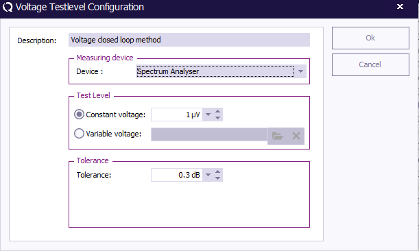
RadiMation® is able to measure the voltage during immunity tests by using a spectrum analyser. When selecting the testlevel/limit/input for the voltage, it is possible to select the measuring device. The selected Device can be changed to Spectrum Analyzer.
Exporting the voltage calibration file[edit]
To perform the required voltage calibration the Voltage closed loop method is used. This method is required to generate the same voltage level, while the power of the measurement locations is measured. This test can be configured using a Multiband Immunity test.
- Create an EUT file that is used to store the calibration measurement results
- Configure a Multiband Immunity test to generate a fixed voltage level over the required frequency range.
- Start the configured test, and wait until the measurement is finished.
- When the test is finished, the data of the measured voltage graphline can be exported to a Calibration file (CAL-File)
- Click the Graphs button above the graph, and select the Export... option
- Select the voltage graphline that should be exported to a Calibration file, then click the Next button
- Select CAL-file as the type of the file to which the graphline should be exported, then click the Export button.
- A Save Calibration as dialog will be shown to determine the location and name where the final calibration file should be stored.
- The exported Calibration file is the result of the 'constant voltage method' for that measurement location. This calibration file can be used during substitution tests to generate a required voltage.
Performing the voltage emission test according to CISPR 25[edit]
For the voltage measurement according to Annex I.5.2.3 of CISPR 25, the following devices and configurations are needed:
Devices:
- HV/LV AN
- EUT
- Signal generator
- Spectrum analyser
Cables corrections: (note: cable corrections are optional)
- Signal generator -> EUT
- EUT -> pre-amp
- Pre-amp -> analyser
Configurations:
- CI module
- Voltage calibration file
- Test level voltage substitution -> using the voltage calibration file
- Test level voltage measurement input -> using analyser as volt measuring device
- Applicable limit lines
Regulating to the calibrated voltage[edit]
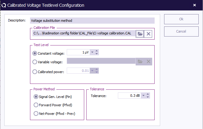
RadiMation® is able to regulate to the voltages determined during the performed voltage calibration.
Measure the voltage using a spectrum analyzer[edit]
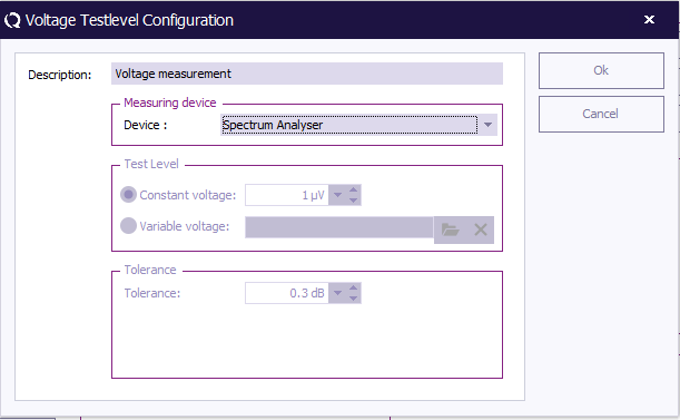
RadiMation® is able to measure the voltage during immunity tests by using a spectrum analyser. When selecting the testlevel/limit/input for the voltage, it is possible to select the measuring device. This selection can be switched to Spectrum Analyzer.
Performing the current emission test according to CISPR 25[edit]
For the current measurement according to Annex I.5.2.4 of CISPR 25, the following devices and configuration are needed:
Devices:
- HV/LV AN
- EUT
- Signal generator
- Spectrum Analyser -> Used as the sensor power meter in test-site
- Current sensor(with correction file containing the transfer factor in Ohm)
Cables corrections: (note: Cable corrections are optional)
- Signal generator -> EUT
- EUT -> pre-amp
- Pre-amp -> analyser
Configurations:
- CI module
- Voltage calibration file
- Test level voltage substitution -> using the voltage calibration file
- Test level input current sensor
- Applicable limit lines
Regulating to the calibrated voltage[edit]
RadiMation® is able to regulate to the voltages determined during the performed voltage calibration.
Measure the current using a spectrum analyser[edit]
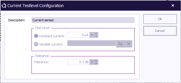
RadiMation® is able to measure the current during immunity tests by using a spectrum analyser as a sensor power meter in combination with a current sensor.
Use a specific detector circuit during current measurements when using an analyser[edit]
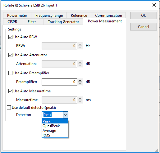
When a spectrum analyser is used as the power meter, it is possible to configure the detector that should be used by the analyser.
This can be configured in the advanced options of the analyser used as power meter
Performing the radiated emission test according to CISPR 25[edit]
For the electrical field strength measurement according to Annex I.5.2.5 of CISPR 25, the following devices and configuration are needed:
Devices:
- HV/LV AN
- EUT
- Signal generator
- Spectrum analyser -> Used as the measuring device for the electrical field
- Calibration antenna with antenna factor correction attached
Cables corrections: (note: Cable corrections are optional)
- Signal generator -> EUT
- EUT -> pre-amp
- Pre-amp -> analyser
Configurations:
- CI module
- Voltage calibration file
- Test level voltage substitution -> using the voltage calibration file
- Test level electrical field input -> using spectrum analyser as field measuring device
- Calibration antenna with correction file containing the antenna factor)
- Applicable limit lines
Regulating to the calibrated voltage[edit]
RadiMation® is able to regulate to the voltages determined during the performed voltage calibration.
Measure the electrical field using a spectrum analyser[edit]
RadiMation® is able to measure the electrical field during immunity tests by using a spectrum analyser + antenna combination.
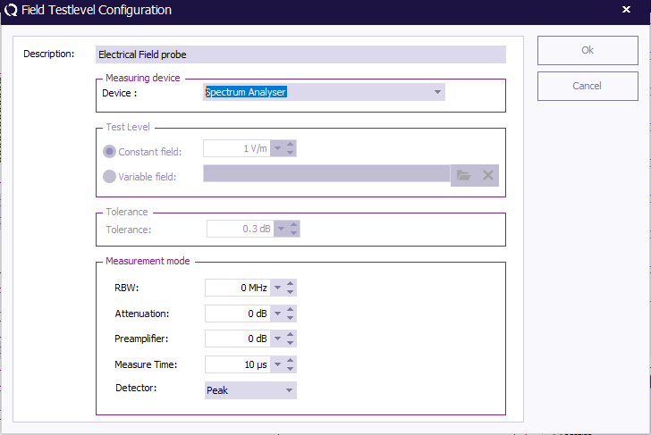
When selecting the testlevel/limit/input for electrical field, it shall now we possible to select the measuring device. This selection can be switched between Field Probe and Spectrum Analyser.
When selecting the Spectrum Analyser as measurement device, other controls will be shown at the bottom of the configuration screen. These controls make it possible to change the following settings which are used by the analyser to measure the electrical field.
- RBW
- Attenuation
- Preamplifier
- Measure Time
- Detector (Peak, Average, Quasi-peak, RMS)
When the spectrum analyser is used as the measuring device, an antenna must also be active in the test site. This antenna is used to attach the .COR file containing the antenna factor which is used to convert the measured voltage(V) returned from the analyser to a electrical field (V/m)
This method of measuring the electrical field uses the antenna factor which is attached to the calibration antenna found in the test-site, because during immunity testing another antenna can already be used to generate the field.
| Note: | When the same antenna is configured for the antenna and calibration antenna slot found in the test-site, the antenna factor found in the .COR shall be merged with it self, when this happens the from voltage converted measured field shall be wrong. So make sure to create separate drivers for a normal antenna and calibration antenna, even if they in fact are the same antenna. |
Configuring limit lines for HV/LV coupling measurements[edit]
Immunity limit lines[edit]
RadiMation® is now able to calculate peaks according to set limit lines in the immunity testing modules.
These peaks indicate the channel name of the input on which the measured value has exceeded the limit line for a certain frequency, as well as the related measurement setting applicable to the moment the peak has been measured.
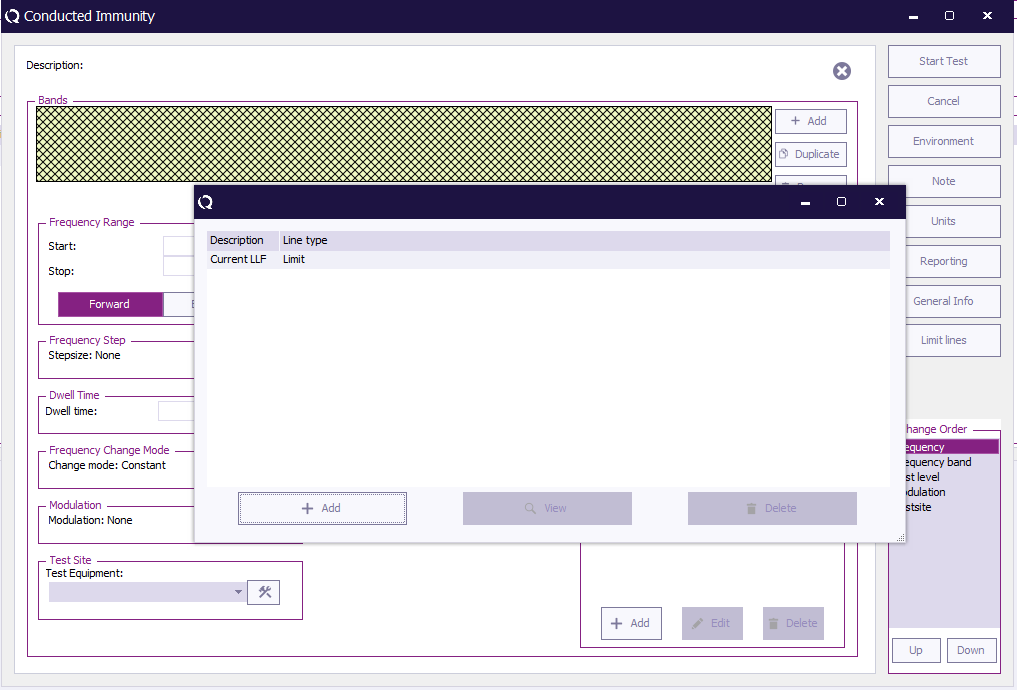
Limit lines can be added to an immunity test by clicking the limit lines button on the right side of the TSF file. This will open a window in which limit lines can be configured for addition or removal.
Peaks are only calculated for testlevels defined as inputs in the TSF- file. All software automatically generated graphlines, as well as test levels, limits and other type of fixed value data are not taken in consideration for the peak calculation.
Changing limit lines after test[edit]
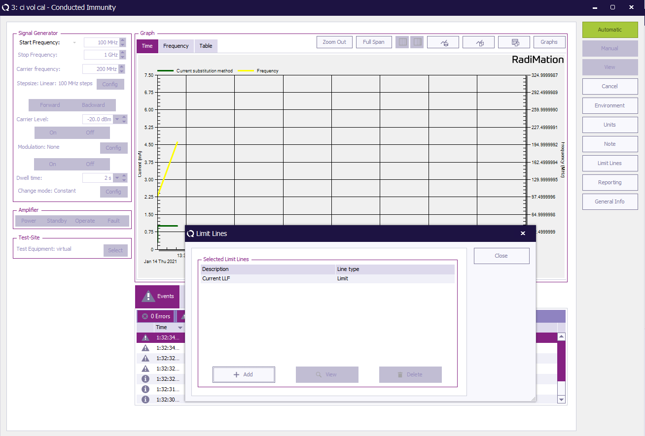
Limit lines can also be changed after a test has finished. This can be done by selecting the limit line control on the right side of the view shown during/after testing.
When a limit line is changed all peaks are recalculated for the new limit line. This also implies that when all limit line are removed, all peaks shall be deleted.
| Note: | Since limit lines can be changed after tests, it is also possible to add limit lines to already performed test which have been created in older RadiMation® releases. |
The peak table for immunity test modules[edit]
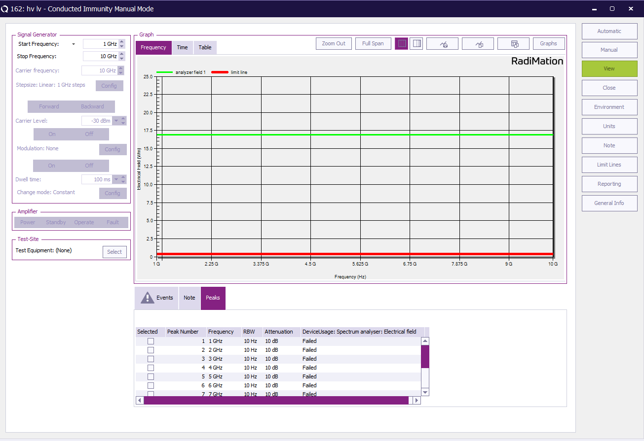
In the view shown while the test is running, it is possible to select the Peaks tab next to the Events and Note tabs. This Peaks tab will show all frequencies, related settings and the channel name of the inputs for which these frequency and settings are applicable.
The peak table is customisable in regards to which columns are shown.
Conclusion[edit]
The RadiMation® multiband immunity test can be used to very accurately measure the leaking of the injected signal form the HV port to the LV port of components that are used in motor vehicles.
Some standards describe that the HV-LV coupling attenuation should be determined between different combinations of lines. That can be achieved by performing the above procedure multiple times where the line on which the signal is injected is different. These EUT measurements can all be performed in the same EUT file. The Note of the test can then for example be used to specify which combination of lines is measured.
