RadiMation Application Note 155: Difference between revisions
No edit summary |
|||
| Line 75: | Line 75: | ||
{{ScreenElementDescription|Test Level|Specify the current substitution method. Also add a "Measured Current Limit"}} | {{ScreenElementDescription|Test Level|Specify the current substitution method. Also add a "Measured Current Limit"}} | ||
{{ScreenElementDescription|Inputs|No inputs are needed.}} | {{ScreenElementDescription|Inputs|No inputs are needed.}} | ||
{{ScreenElementDescriptionEnd}} | |||
At {{ScreenElement|TestLevel}} click {{ScreenElement|Add}} to add a new Test level and select {{ScreenElement|TestLevel - Current closed loop method}} | |||
[[File:CS109 Test level configuration.png]] | |||
{{ScreenElementDescriptionStart}} | |||
{{ScreenElementDescription|Description|The description of the test level.}} | |||
{{ScreenElementDescription|Test level|Variable current, and specify the correction file for the applicable test level.}} | |||
{{ScreenElementDescription|Tolerance|Specify the tolerance to use.}} | |||
{{ScreenElementDescriptionEnd}} | {{ScreenElementDescriptionEnd}} | ||
Revision as of 16:25, 29 November 2023
How to perform a MIL-STD-461 CS109, Conducted susceptibility, structure current test[edit]
This application note explains how the MIL-STD-461 CS109, Conducted susceptibility, structure current test can be performed with RadiMation®
The exact requirements and test methods for the CS109 are specified in the MIL-STD-461.
Necessary equipment[edit]
The following devices are necessary to perform the CS109 test:
- Signal generator
- Amplifier
- Coupling Transformer
- Current sensor
- Cable drivers with corrections
- Sensor power meter / Analyser
- 0.5 Ohm resistor
- Isolation Transformer
Tips[edit]
| Note: | If the current unit is shown as uA, it can be changed to dBuA by clicking Units, select Current and click Edit to change this. |
Define the test level[edit]
Create a correction file for the test level[edit]
-
 File
File
-
 New
New
-
 Correction
-
-
-
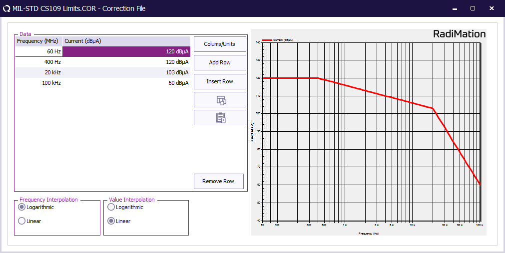
First create a correction file in RadiMation® and specify the test level (See 'FIGURE CS109-1. CS109 limit.').
Ensure that the correction file has a Frequency column and a Current column with the unit set to dBuA.
-
 File
File
-
 Save correction
-
-
Store the test level as correction file on disk.
This correction file with the test level will be used during EUT testing.
EUT Testing[edit]
EUT Testing equipment[edit]
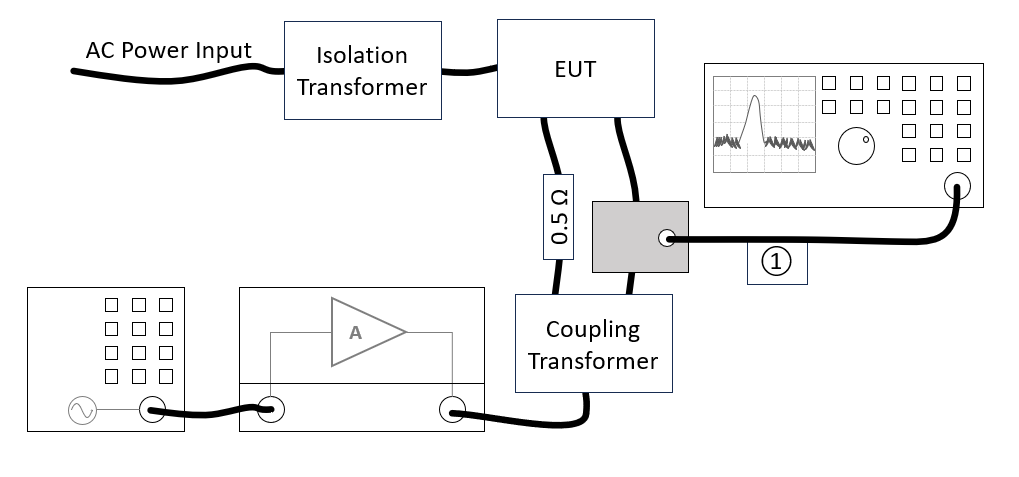
The configuration of the eut test site should contain the following devices:
| # | Device name | Tab in testsite configuration window | note |
|---|---|---|---|
| Signal Generator | Devices 1 | The signal generator to use | |
| Amplifier | Devices 1 | The amplifier to use | |
| Sensor powermeter | Devices 2 | The power meter or analyser to use for measuring the current | |
| Current Sensor | Devices 2 | The current sensor to use with transfer factor attached to the driver | |
| Injection device | Devices 2 | The injection device to use | |
| Cables | |||
| ① | Cable current -> power meter | Cables | Cable (1) with a correction file specified for the cable loss |
Configure the EUT test[edit]
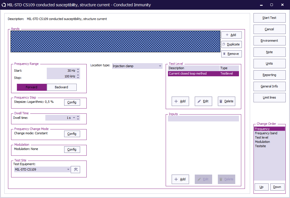
To perform the actual test on the EUT, create a conducted immunity multiband test with 1 band. The conducted immunity multiband test, can be started by selecting from the menu:
-
 Tests
Tests
-
 Conducted Immunity
-
 Multiband
-
-
-
| The start frequency of the test. For example 30 Hz. |
| The stop frequency of the test. For example 100 kHz. |
| The frequency step, see Table III. |
| The dwell time. |
| Constant. |
| CS109 does not specify a modulation to use. |
| The equipment needed for the conducted immunity test. |
| Injection clamp. |
| Specify the current substitution method. Also add a "Measured Current Limit" |
| No inputs are needed. |
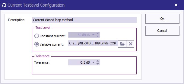
At TestLevel click Add to add a new Test level and select TestLevel - Current closed loop method
| The description of the test level. |
| Variable current, and specify the correction file for the applicable test level. |
| Specify the tolerance to use. |


