Monitoring input channel setup: Difference between revisions
No edit summary |
(→Range) |
||
| (37 intermediate revisions by 3 users not shown) | |||
| Line 1: | Line 1: | ||
Monitoring input channel setup | Monitoring input channel setup | ||
{{Warning|This page is a draft}} | |||
= General = | = General = | ||
This | The Monitoring input channel setup window can be opened by opening a new or existing EUT file: | ||
{{Menu|File|Open|EUT}} or {{Menu|File|New|EUT}} | |||
Then select the 'Monitoring input channels' panel. This window enables the end-user to configure the used AD-Converter during the test: | |||
[[Image:Monitoring input channel setup.png]] | |||
= Settings = | = Settings = | ||
{{ScreenElementDescription|Description|Enter the description of the device. E.g. use the brand and/or identification number.}} | |||
{{ScreenElementDescription|Device| From the dropdown the used AD-Converter driver can be selected.}} | |||
{{ScreenElementDescription|Channel| Based on the selected driver the amount of available channels are shown. In the past only eight channels were allowed. Older devices are still be limited to support a maximum of eight channels in this list, while their driver supports more channels.}} | |||
{{ScreenElementDescription|Unit| Enter the unit corresponding to the values which will be retrieved from the device.}} | |||
= Calculation = | = Calculation = | ||
[[Image:Monitoring input channel setup_calculation.png]] | |||
{{ScreenElementDescription|None|RadiMation will <b>not apply any additional calculations</b> to the value the ''device driver'' is returning. }} | |||
{{ScreenElementDescription|Offset|RadiMation will additionally apply the specified <b>offset</b> to the retrieved value by the ''device driver''. Similar to the formula (<i>offset</i>+x). }} | |||
{{ScreenElementDescription|Multiply|RadiMation will additionally apply the specified <b>multiply factor</b> to the retrieved value by the ''device driver''. Similar to the formula (<i>multiply factor</i>*x). }} | |||
{{ScreenElementDescription|AD input range|RadiMation will <b>not apply any additional calculations</b> to the value the ''device driver'' is returning.}} | |||
{{ScreenElementDescription|Formula y(x)|RadiMation will additionally apply the specified <b>formula</b> to the retrieved value by the ''device driver''. }} | |||
The formula is using the powerful Python engine for maximum flexibility.<br /> | |||
You can find the math functions on: https://docs.python.org/2/library/math.html<br /> | |||
The following example will multiply the AD value by 2. And add (9^0.5)==(√9)==3<br /> | |||
[[File:Formula.png]] | |||
It is needed to match the expected value with the retrieved value by the device driver. Especially for older device driver it is needed to specify the allowed value range of the device. For instance: | |||
[[Image:Monitoring input channel setup calculation old style.png]] | |||
= Measure = | = Measure = | ||
This setting will determine when the measurement will be performed during the test. One or more of the available options can be selected. | |||
{{ScreenElementDescription|Before dwelltime|RadiMation will perform the measurement of the configured monitoring input channel before the start of the dwell-time, just before the selected modulation is being activated.}} | |||
{{ScreenElementDescription|During dwelltime|RadiMation will perform the measurement of the configured monitoring input channel during the dwell-time.}} | |||
{{ScreenElementDescription|After dwelltime|RadiMation will perform the measurement of the configured monitoring input channel after the dwell-time has ended, and the selected modulation has been turned off.}} | |||
= Range = | = Range = | ||
[[Image:Monitoring input channel setup range.png]] | |||
{{ScreenElementDescription|Enable Min Range|This will show a graph line of the specified minimum in the graph and table.}} | |||
{{ScreenElementDescription|Min|The value of the minimum line in the graph and table. }} | |||
{{ScreenElementDescription|Enable Max Range|This will show a graph line of the specified maximum in the graph and table.}} | |||
{{ScreenElementDescription|Max|The value of the maximum line in the graph and table.}} | |||
This information is also used during the 'Minimum Performance' measurements. As long as the measured value from the EUT monitoring input channel is within the specified {{ScreenElement|Min}} and {{ScreenElement|Max}} values, it is assumed that the EUT is not being influenced by the immunity test. If the measured value is above the specified {{ScreenElement|Max}} or below the specified {{ScreenElement|Min}} value, RadiMation assumes that the EUT is being influenced, and the 'Minimum Performance' test will then reduce the generated disturbance. | |||
[[Category:RadiMation]] | [[Category:RadiMation]] | ||
Latest revision as of 21:56, 2 February 2020
Monitoring input channel setup
| Warning: | This page is a draft |
General[edit]
The Monitoring input channel setup window can be opened by opening a new or existing EUT file:
-
 File
File
-
 Open
Open
-
 EUT or
-
-
-
 File
File
-
 New
New
-
 EUT
EUT
-
-
-
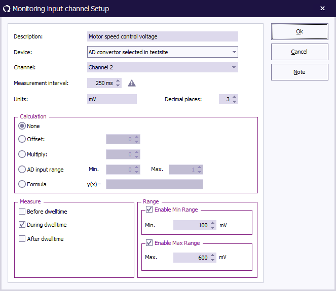
Then select the 'Monitoring input channels' panel. This window enables the end-user to configure the used AD-Converter during the test:
Settings[edit]
| Enter the description of the device. E.g. use the brand and/or identification number. |
| From the dropdown the used AD-Converter driver can be selected. |
| Based on the selected driver the amount of available channels are shown. In the past only eight channels were allowed. Older devices are still be limited to support a maximum of eight channels in this list, while their driver supports more channels. |
| Enter the unit corresponding to the values which will be retrieved from the device. |
Calculation[edit]
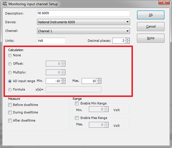
| RadiMation will not apply any additional calculations to the value the device driver is returning. |
| RadiMation will additionally apply the specified offset to the retrieved value by the device driver. Similar to the formula (offset+x). |
| RadiMation will additionally apply the specified multiply factor to the retrieved value by the device driver. Similar to the formula (multiply factor*x). |
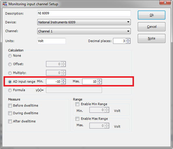
| RadiMation will not apply any additional calculations to the value the device driver is returning. |
| RadiMation will additionally apply the specified formula to the retrieved value by the device driver. |
The formula is using the powerful Python engine for maximum flexibility.
You can find the math functions on: https://docs.python.org/2/library/math.html
The following example will multiply the AD value by 2. And add (9^0.5)==(√9)==3
It is needed to match the expected value with the retrieved value by the device driver. Especially for older device driver it is needed to specify the allowed value range of the device. For instance:
Measure[edit]
This setting will determine when the measurement will be performed during the test. One or more of the available options can be selected.
| RadiMation will perform the measurement of the configured monitoring input channel before the start of the dwell-time, just before the selected modulation is being activated. |
| RadiMation will perform the measurement of the configured monitoring input channel during the dwell-time. |
| RadiMation will perform the measurement of the configured monitoring input channel after the dwell-time has ended, and the selected modulation has been turned off. |
Range[edit]
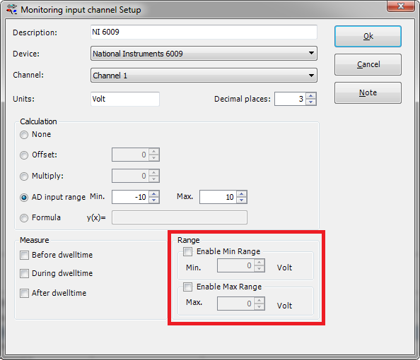
| This will show a graph line of the specified minimum in the graph and table. |
| The value of the minimum line in the graph and table. |
| This will show a graph line of the specified maximum in the graph and table. |
| The value of the maximum line in the graph and table. |
This information is also used during the 'Minimum Performance' measurements. As long as the measured value from the EUT monitoring input channel is within the specified Min and Max values, it is assumed that the EUT is not being influenced by the immunity test. If the measured value is above the specified Max or below the specified Min value, RadiMation assumes that the EUT is being influenced, and the 'Minimum Performance' test will then reduce the generated disturbance.


