CANoe: Difference between revisions
(→CAPL) |
|||
| (46 intermediate revisions by 4 users not shown) | |||
| Line 1: | Line 1: | ||
__NOTOC__ | |||
CANoe and CANalyzer are software packages from [[wikipedia:Vector Informatik|Vector Informatik]] which can be used to control and monitor the [[wikipedia:CAN bus|CAN bus]] or [[wikipedia:Local Interconnect Network|LIN bus]]. | CANoe and CANalyzer are software packages from [[wikipedia:Vector Informatik|Vector Informatik]] which can be used to control and monitor the [[wikipedia:CAN bus|CAN bus]] or [[wikipedia:Local Interconnect Network|LIN bus]]. | ||
It is possible to retrieve measurement values from the CAN bus into RadiMation. And it is also possible to transfer measurement values from RadiMation to the CANoe software, which allows to put the RadiMation measurement values on the CAN bus. | It is possible to retrieve measurement values from the CAN bus into RadiMation. And it is also possible to transfer measurement values from RadiMation to the CANoe software, which allows to put the RadiMation measurement values on the CAN bus. | ||
Each of these data transfer directions can be used in a RadiMation immunity test, and it is even possible to use both data transfer directions in the same immunity test. | Each of these data transfer directions can be used in a RadiMation immunity test, and it is even possible to use both data transfer directions in the same immunity test. | ||
This interface is only working with both CANalyzer and CANoe. We have tested this interface with the Vector Informatik CANoe software and the CANalyzer software version 11 SP2. It is required that the CANoe software or CANalyzer software is installed on the same PC as on which RadiMation is installed. | |||
If you are unfamiliar to CANoe/CANalyzer or would like to know more we advise to read this quickstart guide from Vector: https://assets.vector.com/cms/content/products/VectorCAST/Events/TechNights/CANalyzer_QuickStart.pdf | |||
= Retrieving information from CANoe into RadiMation = | = Retrieving information from CANoe into RadiMation = | ||
| Line 8: | Line 13: | ||
To connect with RadiMation you need to configure the following things: | To connect with RadiMation you need to configure the following things: | ||
<ol> | |||
<li>Start the CANoe software, and load the desired configuration. This can for example be the 'EASY.CFG' example that is included with the CANoe software in the 'CANoe Sample Configurations\CAN\' folder. <BR />[[File:CANoeExample.png]]</li> | |||
<li>Start the RadiMation software.</li> | |||
<li>Go to the AD device driver configuration window. <BR />{{Menu|Configuration|Configuration|Device Drivers|AD Convertors}}</li> | |||
<li>Create the [[CANoe Interface]] device driver (as an AD Convertor) in RadiMation.</li> | |||
<li>Open the 'Advanced' settings window of the {{ScreenElement|CANoe Interface}} device driver. <BR />[[File:CANoe AD Convertor.png]]<BR>Use the {{ScreenElement|Set up}} buttons to select up to 8 measurement values from the CAN bus, that should be transferred to RadiMation. When the {{ScreenElement|Set up}} button is pressed (for example for {{ScreenElement|Channel 1}}), a CANoe signal selection dialog is shown.<BR />[[File:CANoe AD Convertor signal selector.png]]<BR />This dialog allows to select the desired signal, for example the '''Signals::easy::EngineState::EngineSpeed''' signal.</li> | |||
<li>Close all dialogs by pressing {{ScreenElement|Select}}, {{ScreenElement|Ok}} and {{ScreenElement|Close}}. | |||
<li>In the EUT window in RadiMation, specify an EUT monitoring input channel for the channel 1. <BR />[[File:CANoe EUT Monitoring Input Setup.png]]<BR /> | |||
By selecting the correct {{ScreenElement|Device}} and {{ScreenElement|Channel}}, a link to the already configured [[CANoe Interface]] device driver will be created. | |||
No re-calculation of the value is needed, so it is sufficient to select {{ScreenElement|None}} as the {{ScreenElement|Calculation}} method. | |||
When an immunity test is started, all the activated EUT Monitoring inputs will be measured on each | For each additional configured channel that is selected in the '''CANoe Interface''' device driver, a matching EUT Monitoring input should also be configured.</li> | ||
</ol> | |||
When an immunity test is started, all the activated EUT Monitoring inputs will be measured on each tested frequency, and thus the data from the CAN bus (through the CANoe software) will also be included in RadiMation, and will be shown in the graphs. | |||
== Retrieving CANoe system variables == | |||
The CANoe signal selection dialog also allows to select CANoe system variables. The values of those CANoe system variables, can thus also be retrieved and shown in RadiMation during an immunity test. However, be aware that when monitoring CANoe system variables, only the following types are supported: | |||
* Integer (32 Bit signed) | |||
* Integer (64 Bit signed) | |||
* Double (64 Bit) | |||
* String | |||
[[File:CANoeSystemVariables.png]] | |||
= Supplying RadiMation values to CANoe = | = Supplying RadiMation values to CANoe = | ||
It is possible to supply RadiMation values to CAN bus through the CANoe | It is possible to supply RadiMation values to the CAN bus through the CANoe software. The exact details on how this should be done is however completely depending on the implementation of the units on the CAN bus itself. To allow the flexibility to adjust and adapt to the messages on the CAN bus, RadiMation is calling specific CAPL functions, which can be customized to perform the desired and applicable action. Using this CAPL interface allows for full flexibility on the implementation and details, or how the measurement information should be transmitted on the CAN bus. | ||
== CAPL == | == CAPL interface == | ||
CANoe supports | CANoe supports CAPL, a programming interface designed by [[wikipedia:Vector Informatik|Vector Informatik]]. Through this interface, RadiMation can send updated measurement values to the running CANoe environment. | ||
This does include the following measurement values: | |||
* Frequency | * Frequency | ||
* Field Strength | * Field Strength | ||
| Line 32: | Line 55: | ||
* ... (and more) | * ... (and more) | ||
RadiMation | RadiMation is calling specifically named CAPL functions. Those CAPL functions are specified in the [[RadiMationInterface.can]] file. | ||
To include the [[RadiMationInterface.can]] file in your CANoe project, you should take the following steps: | |||
# Download the ZIP file from the [[RadiMationInterface.can]] page. | |||
# Extract the [[RadiMationInterface.can]] file from the ZIP file, and store it on a suitable location | |||
# Start the CANoe software and load the desired configuration. That can for example be the 'EASY.CFG' example that is included with the CANoe software in the 'CANoe Sample Configuration\CAN\' folder. | |||
# Switch to the Simulation Setup view within CANoe.<BR />[[File:CANoe Simulation setup.png]] | |||
# Add a new Node to the simulation setup. This can for example be done by right-clicking on the horizontal red lines, and then select the '''Insert ...''' menu entry. It will allow to select the correct *.CAN file, which could for example be the [[RadiMationInterface.can]] file. | |||
To configure RadiMation to call the CAPL functions, the following steps should be performed: | |||
<ol> | |||
<li>Go to the Switch matrix device driver driver configuration window. {{Menu|Configuration|Configuration|Device drivers|Switch matrixes}}.</li> | |||
<li>Create the [[CANoe Switch Matrix]] device driver in RadiMation. No further configuration of this device driver is needed.</li> | |||
<li>Select the created [[CANoe Switch Matrix]] device driver in the testsite that is used during the immunity test.</li> | |||
</ol> | |||
When now an immunity test is started, the [[CANoe Switch Matrix]] device driver will call the functions in the [[RadiMationInterface.can]] file that is included in the running CANoe environment. | |||
[[File:CANoe CAPL messages.png]] | |||
The functions that are included in the [[RadiMationInterface.can]] file only provide a very simple implementation where the received updates of the measurement values are written to the console in CANoe (see the screenshot above). Depending on the requirements of the connected CAN bus, those functions can however be extended to perform other actions, like transmitting a message on the CAN bus. | |||
Note that the functions in the [[RadiMationInterface.can]] file do not support a callback to the RadiMation application. So this CAPL interface can only be used to send updates of measurement values during a test from [[RadiMation]] to CANoe. | |||
= Using CANalyzer with CAPL/CANoe Switch matrix = | |||
Instead of CANoe one can also use CANalyzer to display the values transmitted from RadiMation. | |||
One can use the CANoe Switchmatrix to do this. It will recognize if CANalyzer is installed and will start the software if CANoe is not available. | |||
To configure RadiMation to call the CAPL functions, the following steps should be performed: | |||
<ol> | |||
<li>Go to the Switch matrix device driver driver configuration window. {{Menu|Configuration|Configuration|Device drivers|Switch matrixes}}.</li> | |||
<li>Create the [[CANoe Switch Matrix]] device driver in RadiMation. No further configuration of this device driver is needed.</li> | |||
<li>Select the created [[CANoe Switch Matrix]] device driver in the testsite that is used during the immunity test.</li> | |||
</ol> | |||
Now add the [[RadiMationInterface.can]] to CANalyzer. This is the script defining the parameters that need to be sent. | |||
<ol> | |||
# Download the zip file from the [[RadiMationInterface.can]] file. | |||
# Open up CANalyzer | |||
# Go to “Analysis & Stimulation”/”Measurement Setup”<BR /> [[File:MeasurementSetup.png]] | |||
# Go to configuration:<BR /> [[File:configuration.png]] | |||
# "Right click" on a node<BR /> [[File:InsterNodeCircle.png]] | |||
# Select “Insert Program Node, the node should now be inserted.<BR /> [[File:InsertNode.png]] | |||
# Right click on the node and click "Configuration" | |||
# Click "Select" | |||
# Load the file: [[RadiMationInterface.can]] and when loaded correctly the screen should look like this:<BR /> [[File:Inderface.can.png]] | |||
# Now press compile to make sure that the script is properly initiated. | |||
==Test the CAPL coupling between Radimation and CANalyzer== | |||
Setup a CAPL switch matrix. Add this to a radiated immunity test-site. Now start a single-band RI test. | |||
During initialization CANalyzer is launched and you should see the data coming in CANalyzer, see above for the exact procedure. | |||
In the example below a RI substitution single band test is used to verify.<BR /> [[File:RiSubstitution.png]]<BR /> | |||
When running the test CANalyzer will start automatically and will start to receive the data from Radimation.<BR /> [[File:Canalyzer.png]]<BR /> | |||
==Summary== | |||
CANalyzer and RadiMation are now properly set-up. Every time a test is started with a test-site that includes a CANoe switch matrix, CANalyzer or CANoe is automatically started. | |||
Latest revision as of 14:47, 3 October 2024
CANoe and CANalyzer are software packages from Vector Informatik which can be used to control and monitor the CAN bus or LIN bus.
It is possible to retrieve measurement values from the CAN bus into RadiMation. And it is also possible to transfer measurement values from RadiMation to the CANoe software, which allows to put the RadiMation measurement values on the CAN bus. Each of these data transfer directions can be used in a RadiMation immunity test, and it is even possible to use both data transfer directions in the same immunity test.
This interface is only working with both CANalyzer and CANoe. We have tested this interface with the Vector Informatik CANoe software and the CANalyzer software version 11 SP2. It is required that the CANoe software or CANalyzer software is installed on the same PC as on which RadiMation is installed.
If you are unfamiliar to CANoe/CANalyzer or would like to know more we advise to read this quickstart guide from Vector: https://assets.vector.com/cms/content/products/VectorCAST/Events/TechNights/CANalyzer_QuickStart.pdf
Retrieving information from CANoe into RadiMation[edit]
Use the CANoe Interface AD Convertor device driver to read out measurement values from the CANoe Software into RadiMation.
To connect with RadiMation you need to configure the following things:
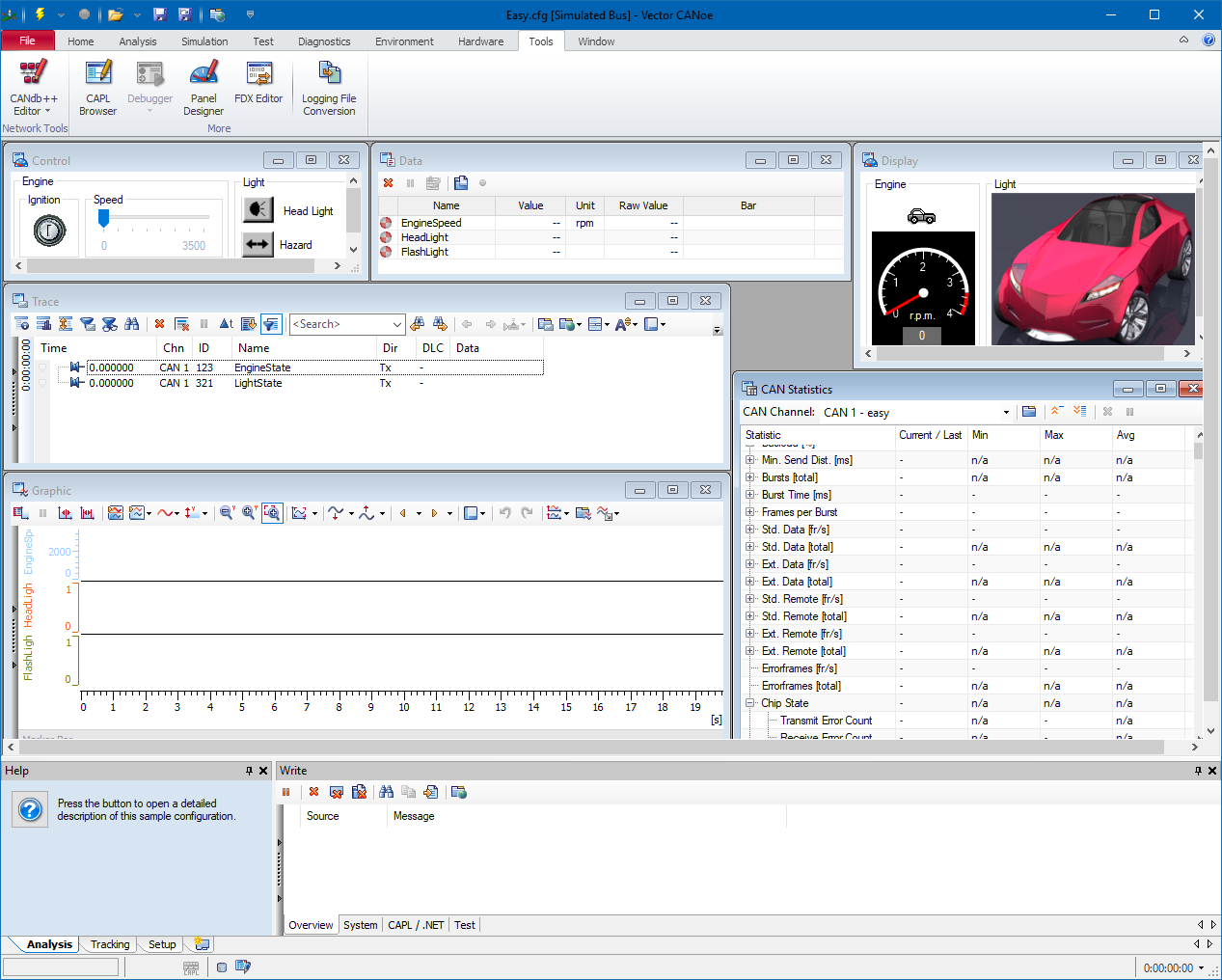
- Start the CANoe software, and load the desired configuration. This can for example be the 'EASY.CFG' example that is included with the CANoe software in the 'CANoe Sample Configurations\CAN\' folder.
- Start the RadiMation software.
- Go to the AD device driver configuration window.
-
 Configuration
-
 Configuration
-
 Device Drivers
-
 AD Convertors
-
-
-
-
- Create the CANoe Interface device driver (as an AD Convertor) in RadiMation.
- Open the 'Advanced' settings window of the CANoe Interface device driver.
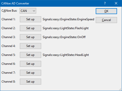
Use the Set up buttons to select up to 8 measurement values from the CAN bus, that should be transferred to RadiMation. When the Set up button is pressed (for example for Channel 1), a CANoe signal selection dialog is shown.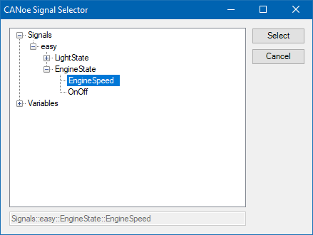
This dialog allows to select the desired signal, for example the Signals::easy::EngineState::EngineSpeed signal. - Close all dialogs by pressing Select, Ok and Close.
- In the EUT window in RadiMation, specify an EUT monitoring input channel for the channel 1.
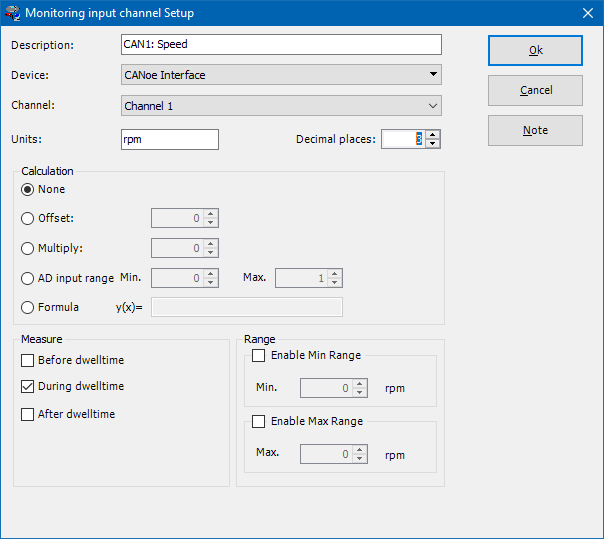
By selecting the correct Device and Channel, a link to the already configured CANoe Interface device driver will be created. No re-calculation of the value is needed, so it is sufficient to select None as the Calculation method. For each additional configured channel that is selected in the CANoe Interface device driver, a matching EUT Monitoring input should also be configured.
When an immunity test is started, all the activated EUT Monitoring inputs will be measured on each tested frequency, and thus the data from the CAN bus (through the CANoe software) will also be included in RadiMation, and will be shown in the graphs.
Retrieving CANoe system variables[edit]
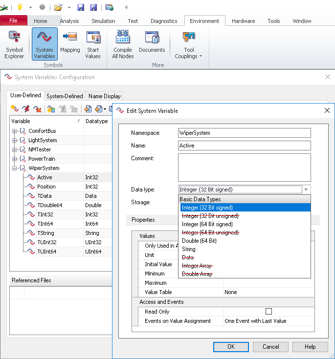
The CANoe signal selection dialog also allows to select CANoe system variables. The values of those CANoe system variables, can thus also be retrieved and shown in RadiMation during an immunity test. However, be aware that when monitoring CANoe system variables, only the following types are supported:
- Integer (32 Bit signed)
- Integer (64 Bit signed)
- Double (64 Bit)
- String
Supplying RadiMation values to CANoe[edit]
It is possible to supply RadiMation values to the CAN bus through the CANoe software. The exact details on how this should be done is however completely depending on the implementation of the units on the CAN bus itself. To allow the flexibility to adjust and adapt to the messages on the CAN bus, RadiMation is calling specific CAPL functions, which can be customized to perform the desired and applicable action. Using this CAPL interface allows for full flexibility on the implementation and details, or how the measurement information should be transmitted on the CAN bus.
CAPL interface[edit]
CANoe supports CAPL, a programming interface designed by Vector Informatik. Through this interface, RadiMation can send updated measurement values to the running CANoe environment.
This does include the following measurement values:
- Frequency
- Field Strength
- Signal power
- Forward power
- Current
- Turntable angle
- Antenna height
- Antenna polarization
- ... (and more)
RadiMation is calling specifically named CAPL functions. Those CAPL functions are specified in the RadiMationInterface.can file.
To include the RadiMationInterface.can file in your CANoe project, you should take the following steps:
- Download the ZIP file from the RadiMationInterface.can page.
- Extract the RadiMationInterface.can file from the ZIP file, and store it on a suitable location
- Start the CANoe software and load the desired configuration. That can for example be the 'EASY.CFG' example that is included with the CANoe software in the 'CANoe Sample Configuration\CAN\' folder.
- Switch to the Simulation Setup view within CANoe.
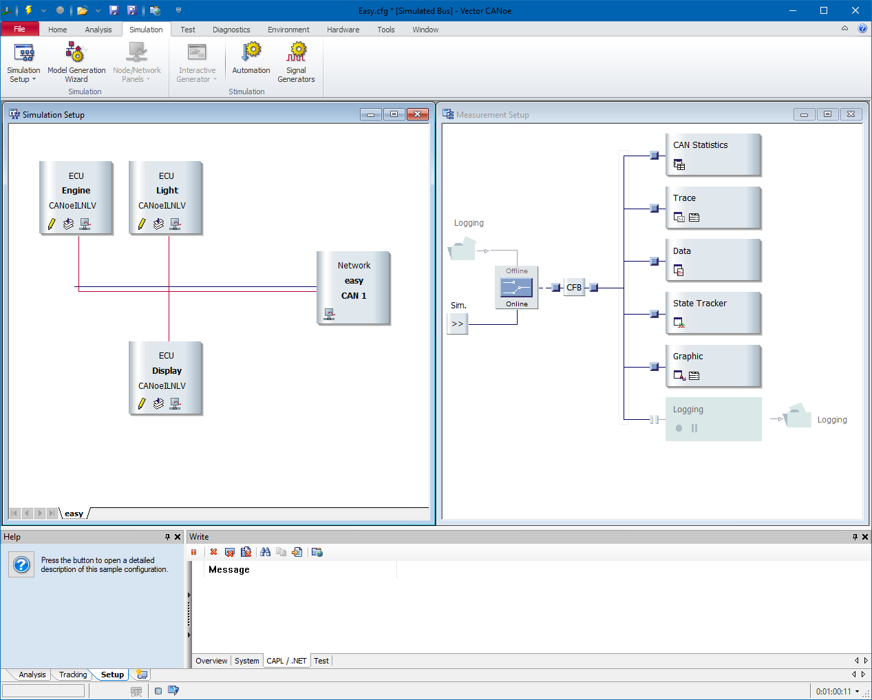
- Add a new Node to the simulation setup. This can for example be done by right-clicking on the horizontal red lines, and then select the Insert ... menu entry. It will allow to select the correct *.CAN file, which could for example be the RadiMationInterface.can file.
To configure RadiMation to call the CAPL functions, the following steps should be performed:
- Go to the Switch matrix device driver driver configuration window.
-
 Configuration
-
 Configuration
-
 Device drivers
-
 Switch matrixes .
-
-
-
-
- Create the CANoe Switch Matrix device driver in RadiMation. No further configuration of this device driver is needed.
- Select the created CANoe Switch Matrix device driver in the testsite that is used during the immunity test.
When now an immunity test is started, the CANoe Switch Matrix device driver will call the functions in the RadiMationInterface.can file that is included in the running CANoe environment.
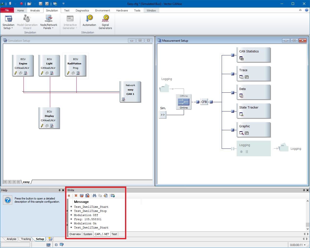
The functions that are included in the RadiMationInterface.can file only provide a very simple implementation where the received updates of the measurement values are written to the console in CANoe (see the screenshot above). Depending on the requirements of the connected CAN bus, those functions can however be extended to perform other actions, like transmitting a message on the CAN bus.
Note that the functions in the RadiMationInterface.can file do not support a callback to the RadiMation application. So this CAPL interface can only be used to send updates of measurement values during a test from RadiMation to CANoe.
Using CANalyzer with CAPL/CANoe Switch matrix[edit]
Instead of CANoe one can also use CANalyzer to display the values transmitted from RadiMation.
One can use the CANoe Switchmatrix to do this. It will recognize if CANalyzer is installed and will start the software if CANoe is not available.
To configure RadiMation to call the CAPL functions, the following steps should be performed:
- Go to the Switch matrix device driver driver configuration window.
-
 Configuration
-
 Configuration
-
 Device drivers
-
 Switch matrixes .
-
-
-
-
- Create the CANoe Switch Matrix device driver in RadiMation. No further configuration of this device driver is needed.
- Select the created CANoe Switch Matrix device driver in the testsite that is used during the immunity test.
Now add the RadiMationInterface.can to CANalyzer. This is the script defining the parameters that need to be sent.
- Download the zip file from the RadiMationInterface.can file.
- Open up CANalyzer
- Go to “Analysis & Stimulation”/”Measurement Setup”
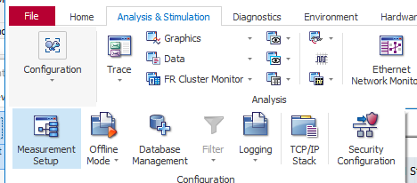
- Go to configuration:

- "Right click" on a node
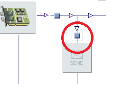
- Select “Insert Program Node, the node should now be inserted.
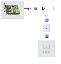
- Right click on the node and click "Configuration"
- Click "Select"
- Load the file: RadiMationInterface.can and when loaded correctly the screen should look like this:
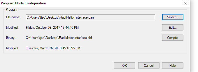
- Now press compile to make sure that the script is properly initiated.
Test the CAPL coupling between Radimation and CANalyzer[edit]
Setup a CAPL switch matrix. Add this to a radiated immunity test-site. Now start a single-band RI test. During initialization CANalyzer is launched and you should see the data coming in CANalyzer, see above for the exact procedure.
In the example below a RI substitution single band test is used to verify.
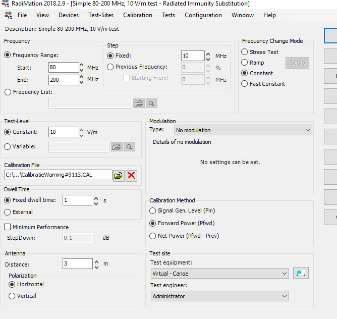
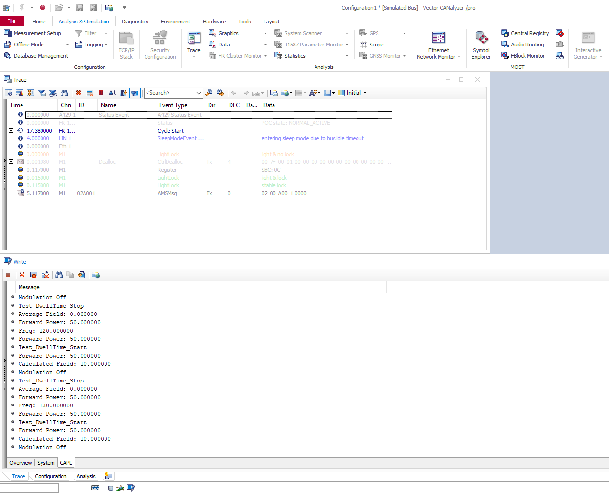
When running the test CANalyzer will start automatically and will start to receive the data from Radimation.
Summary[edit]
CANalyzer and RadiMation are now properly set-up. Every time a test is started with a test-site that includes a CANoe switch matrix, CANalyzer or CANoe is automatically started.
