RadiMation Application Note 123: Difference between revisions
(Created page with " RadiMation Application Note 123 Jump to:navigation, search Implementing Switch Matrix design in RadiMation®[edit] This application note describes how to implement a switch...") |
|||
| (54 intermediate revisions by 2 users not shown) | |||
| Line 1: | Line 1: | ||
__NOTOC__ | |||
= Implementing the control of a switch matrix in {{RadiMation}} = | |||
This application note explains how to integrate a switch matrix into {{RadiMation}} so that the actual relays are correctly controlled when the automated test is performed by {{RadiMation}}. | |||
RadiMation | When performing a test, it is often necessary to switch between different pieces of equipment depending on the settings or frequency range. {{RadiMation}} supports this by allowing a specific switch matrix driver to be configured for each test site. | ||
Normally the actual physical configuration of one or more relays and the related cabling and connections is available as a schematic drawing or listed in for example a Microsoft Excel sheet. It provides which components are connected to each other when the relays are in a certain state. SPDT ([[wikipedia:Single pole, double throw|single pole, double throw]]) relays normally can be in two modes, being: 'Normally Open' (NO) and 'Normally Closed' (NC). Other relay types like SP6T (single pole, 6 throw, or a one on 6-relay), indicate a specific switch state with the actual position number. | |||
* 'Normally Closed' (NC) indicates the state of the relay when it is completely un-powered, and thus is the state in which it returns when it is being disconnected. | |||
* 'Normally Open' (NO) indicates the contact that closes (i.e., makes the connection) only when the relay is powered; when un-powered it is open (not connected). To make a connection on the 'Normally open' state, the relay has to be actively controlled. | |||
Based on these states, and the actual physical switch matrix design the exact flow of the signals is known, and it can be determined which switches need to be set to create the desired signal path. | |||
== A radiated immunity test with two frequency bands == | |||
To activate a desired signal path, switch matrix device drivers with the correct settings need to be selected in the test site. | |||
A simple possible scenario where a switch matrix can be used is the automation of a Radiated Immunity system that has different amplifiers and different antennas to cover the frequency range from 80 MHz up to 3 GHz. The equipment that can be used for this is: | |||
{|class="wikitable" | |||
! Test site || device type || model || frequency range || remark | |||
|- | |||
!colspan="5"| Radiated Immunity - 80 MHz - 1 GHz | |||
|- | |||
| || Amplifier || [[ETS-Lindgren 8100-002]] || 80 MHz - 1 GHz || | |||
|- | |||
| || Coupler || [[Bonn BDC 0110-40]] || 100 kHz - 1 GHz || | |||
|- | |||
| || Antenna|| [[Schwarzbeck VULB 9160]] || 80 MHz - 1.7 GHz || | |||
|- | |||
!colspan="5"| Radiated Immunity - 1 GHz - 3 GHz | |||
|- | |||
| || Amplifier || [[Bonn BLMA 1030-250]] || 1 GHz - 3 GHz || | |||
|- | |||
| || Coupler || [[Bonn BDC 0530-50]] || 500 MHz - 3 GHz || | |||
|- | |||
| || Antenna|| [[Schwarzbeck BBHA 9120D]] || 1 GHz - 18 GHz || | |||
|- | |||
!colspan="5"| Generic / used in both | |||
|- | |||
| || Signal generator || [[Raditeq RGN2006B|RadiGen RGN2006B]] || 4 kHz - 6 GHz || | |||
|- | |||
| || Forward power meter || [[Raditeq RPR2006C|RadiPower RPR2006C]] (Fwd) || 9 kHz - 6 GHz || | |||
|- | |||
| || Reflected power meter || [[Raditeq RPR2006C|RadiPower RPR2006C]] (Refl) || 9 kHz - 6 GHz || | |||
|- | |||
| || N-type relay (Relay A) || [[Raditeq RSW1021N|RadiSwitch RSW1021N]] || DC - 12.4 GHz || present in RadiCentre slot 4 | |||
|- | |||
| || N-type relay (Relay B) || [[Raditeq RSW1021N|RadiSwitch RSW1021N]] || DC - 12.4 GHz || present in RadiCentre slot 5 | |||
|- | |||
| || N-type relay (Relay C) || [[Raditeq RSW1021N|RadiSwitch RSW1021N]] || DC - 12.4 GHz || present in RadiCentre slot 6 | |||
|} | |||
Apart from this equipment also two power meters to measure the forward and reflected power are used. A single signal generator is used to drive the amplifiers. | |||
See the picture below for a schematic overview of this setup. In this diagram the cables for the forward power are drawn in red, while the cables for the reflected power are drawn in blue. | |||
See the | |||
In | |||
[[File:ApplicationNote123Switches.png]] | |||
The signal path and devices needed in the different bands need to be different, while at the other hand some equipment (like the signal generator and power meters) are the same for both signal paths. To configure the differences, it is necessary to make two test sites. The first test site is for testing on the the low frequency range and the second test site is for testing on the high frequency range. During the actual test configuration, the desired test site for the frequency range can be selected that is applicable. And because the test site configuration also contains the correct switch matrix configuration, also the relays will be automatically set to create the correct signal path. | |||
The correct position of each relay for each test site will be: | |||
{|class="wikitable" | |||
! Test site || Relay A || Relay B || Relay C | |||
|- | |||
| Radiated Immunity - 80 MHz - 1 GHz || NC || NC || NC | |||
|- | |||
| Radiated Immunity - 1 GHz - 3 GHz || NO || NO || NO | |||
|} | |||
This switch matrix design can now be implemented in {{RadiMation}} by configuring the different components. In this example, separate switches are being used, however it is also possible to use switchboards that have more than one relay, and in that case a single switchmatrix device driver for each test site can suffice. | |||
== Configuring and using switches in RadiMation == | |||
Once all the information and the schematic is defined, all the used devices can be configured in {{RadiMation}}. The most logical configuration is to create a switch matrix for each individual signal path (or part of the signal path) that can be active at any moment. A switch matrix device driver is thus not created for a single relay, but each possible switch selection of a relay will have its own switch matrix device driver. The activated relay selection is thus part of each switch matrix device driver. | |||
== Configuring the switch matrix device drivers for all relays == | |||
<ol> | |||
<li>Open the menu<p>{{Menu|Configuration|Configuration|Device Drivers}}</p></li> | |||
<li>Choose the device type {{ScreenElement|Switch matrixes}} and click on {{ScreenElement|Add}}.</li> | |||
<li>From the list, select the {{ScreenElement|Raditeq RSW1021N}}.</li> | |||
<li>Set the description to the state that is actually being selected by the driver in this example: <code>Signal generator to ETS-Lindgren amplifier</code>. <BR />[[File:ApplicationNote123RelayAName.png]]</li> | |||
<li>Open the {{ScreenElement|Advanced}} driver configuration and go to the {{ScreenElement|Communication}} tab. Configure the correct communication settings to control the relay card, depending on how it is connected to the PC.<BR />[[File:ApplicationNote123RelayACommunication.png]]</li> | |||
<li>For the [[Raditeq RSW1021N]] relay, also the RadiCentre slot number in which the card is present should be selected. Select the {{ScreenElement|RadiCentre}} tab, and select the correct slot number, which is 4 for Relay A in the example setup.<BR />[[File:ApplicationNote123RelayARadiCentre.png]]</li> | |||
<li> Select the {{ScreenElement|Switches}} tab and select {{ScreenElement|Normally Closed}} for the relay in the {{ScreenElement|During}} phase. The relay position that is selected on the {{ScreenElement|During}} tab is the relay position that is active ''''during'''' the test. The relay position that is selected on the {{ScreenElement|After}} tab is the relay position that is active ''''after'''' the test is finished. <BR />[[File:ApplicationNote123RelayASwitches.png]]</li> | |||
<li>Close the advanced driver configuration.</li> | |||
</ol> | |||
Repeat the above steps to also create drivers for all the other signal paths of Relay A, Relay B and Relay C: | |||
{|class="wikitable" | |||
! Relay || device driver name || RadiCentre slot number || internal relay state | |||
|- | |||
| Relay A || Signal generator to ETS-Lindgren amplifier || 4 || Normally closed | |||
|- | |||
| Relay A || Signal generator to Bonn amplifier || 4 || Normally open | |||
|- | |||
| Relay B || ETS-Lindgren amplifier to forward power meter|| 5 || Normally closed | |||
|- | |||
| Relay B || Bonn amplifier to forward power meter || 5 || Normally open | |||
|- | |||
| Relay C || ETS-Lindgren amplifier to reflected power meter|| 6 || Normally closed | |||
|- | |||
| Relay C || Bonn amplifier to reflected power meter || 6 || Normally open | |||
|} | |||
After these switch matrix device drivers are created, the list of configured device drivers is available as: | |||
[[File:ApplicationNote123SwitchMatrixDeviceDrivers.png]] | |||
== Selecting the switch matrix device drivers in the test site == | |||
Once all the device drivers for the switch matrix states and the other test and measurement equipment are created, those device drivers can be selected in the corresponding test site configuration. | |||
In the provided example, two test sites are being used, each having their own operational frequency range. | |||
<ol> | |||
<li>Open the test site configuration by selecting from the menu<p>{{Menu|Configuration|Test Equipment}}</p></li> | |||
<li>Click on {{ScreenElement|Add}} to make a new test site, and specify the name of the new test site: "Radiated Immunity - 80 MHz - 1 GHz"</li> | |||
<li>Now {{ScreenElement|Add}} all the device drivers for this test site, needed to perform the test. In this example that would be: | |||
* Signal generator: RadiGen RGN2006B | |||
* Amplifier: ETS-Lindgren 8100-002 | |||
* Coupler: Bonn BDC 0110-40 | |||
* Forward power meter: RadiPower RPR2006C (Fwd) | |||
* Reflected power meter: RadiPower RPR2006C (Refl) | |||
* Antenna: Schwarzbeck VULB 9160</li> | |||
<li>Also add the previously created switch-matrix device drivers. More than 1 switch matrix device driver can be selected in the test site configuration: | |||
* Switch matrix: Signal generator to ETS-Lindgren amplifier | |||
* Switch matrix: ETS-Lindgren amplifier to forward power meter | |||
* Switch matrix: ETS-Lindgren amplifier to reflected power meter</li> | |||
<li>Close the test site configuration, by clicking on {{ScreenElement|Save}} and {{ScreenElement|Close}}</li> | |||
</ol> | |||
The test site configuration is now thus available as: | |||
[[File:ApplicationNote123LowFrequencyTestsite.png]] | |||
Similarly, the test site configuration for "Radiated Immunity - 1 GHz - 3 GHz" can be created, with all the relevant device drivers, and switch matrix device drivers that are applicable for the high frequency range. That test site configuration will then be available as: | |||
[[File:ApplicationNote123HighFrequencyTestsite.png]] | |||
== Conclusion == | |||
By using one or more switch matrix device drivers, it is possible to create fully automated control of the relay switching when the {{RadiMation}} test is started. This example shows how this can be implemented for a low frequency signal path and a high frequency signal path in a Radiated Immunity test. The same technique by creating switch matrix device drivers is also working in other tests like Conducted Emission, and all the other {{RadiMation}} modules. | |||
[[Category:RadiMation Application Note]] | |||
[[Category:RadiMation]] | |||
Latest revision as of 15:04, 5 November 2025
Implementing the control of a switch matrix in RadiMation®[edit]
This application note explains how to integrate a switch matrix into RadiMation® so that the actual relays are correctly controlled when the automated test is performed by RadiMation®.
When performing a test, it is often necessary to switch between different pieces of equipment depending on the settings or frequency range. RadiMation® supports this by allowing a specific switch matrix driver to be configured for each test site.
Normally the actual physical configuration of one or more relays and the related cabling and connections is available as a schematic drawing or listed in for example a Microsoft Excel sheet. It provides which components are connected to each other when the relays are in a certain state. SPDT (single pole, double throw) relays normally can be in two modes, being: 'Normally Open' (NO) and 'Normally Closed' (NC). Other relay types like SP6T (single pole, 6 throw, or a one on 6-relay), indicate a specific switch state with the actual position number.
- 'Normally Closed' (NC) indicates the state of the relay when it is completely un-powered, and thus is the state in which it returns when it is being disconnected.
- 'Normally Open' (NO) indicates the contact that closes (i.e., makes the connection) only when the relay is powered; when un-powered it is open (not connected). To make a connection on the 'Normally open' state, the relay has to be actively controlled.
Based on these states, and the actual physical switch matrix design the exact flow of the signals is known, and it can be determined which switches need to be set to create the desired signal path.
A radiated immunity test with two frequency bands[edit]
To activate a desired signal path, switch matrix device drivers with the correct settings need to be selected in the test site.
A simple possible scenario where a switch matrix can be used is the automation of a Radiated Immunity system that has different amplifiers and different antennas to cover the frequency range from 80 MHz up to 3 GHz. The equipment that can be used for this is:
| Test site | device type | model | frequency range | remark |
|---|---|---|---|---|
| Radiated Immunity - 80 MHz - 1 GHz | ||||
| Amplifier | ETS-Lindgren 8100-002 | 80 MHz - 1 GHz | ||
| Coupler | Bonn BDC 0110-40 | 100 kHz - 1 GHz | ||
| Antenna | Schwarzbeck VULB 9160 | 80 MHz - 1.7 GHz | ||
| Radiated Immunity - 1 GHz - 3 GHz | ||||
| Amplifier | Bonn BLMA 1030-250 | 1 GHz - 3 GHz | ||
| Coupler | Bonn BDC 0530-50 | 500 MHz - 3 GHz | ||
| Antenna | Schwarzbeck BBHA 9120D | 1 GHz - 18 GHz | ||
| Generic / used in both | ||||
| Signal generator | RadiGen RGN2006B | 4 kHz - 6 GHz | ||
| Forward power meter | RadiPower RPR2006C (Fwd) | 9 kHz - 6 GHz | ||
| Reflected power meter | RadiPower RPR2006C (Refl) | 9 kHz - 6 GHz | ||
| N-type relay (Relay A) | RadiSwitch RSW1021N | DC - 12.4 GHz | present in RadiCentre slot 4 | |
| N-type relay (Relay B) | RadiSwitch RSW1021N | DC - 12.4 GHz | present in RadiCentre slot 5 | |
| N-type relay (Relay C) | RadiSwitch RSW1021N | DC - 12.4 GHz | present in RadiCentre slot 6 | |
Apart from this equipment also two power meters to measure the forward and reflected power are used. A single signal generator is used to drive the amplifiers.
See the picture below for a schematic overview of this setup. In this diagram the cables for the forward power are drawn in red, while the cables for the reflected power are drawn in blue.

The signal path and devices needed in the different bands need to be different, while at the other hand some equipment (like the signal generator and power meters) are the same for both signal paths. To configure the differences, it is necessary to make two test sites. The first test site is for testing on the the low frequency range and the second test site is for testing on the high frequency range. During the actual test configuration, the desired test site for the frequency range can be selected that is applicable. And because the test site configuration also contains the correct switch matrix configuration, also the relays will be automatically set to create the correct signal path.
The correct position of each relay for each test site will be:
| Test site | Relay A | Relay B | Relay C |
|---|---|---|---|
| Radiated Immunity - 80 MHz - 1 GHz | NC | NC | NC |
| Radiated Immunity - 1 GHz - 3 GHz | NO | NO | NO |
This switch matrix design can now be implemented in RadiMation® by configuring the different components. In this example, separate switches are being used, however it is also possible to use switchboards that have more than one relay, and in that case a single switchmatrix device driver for each test site can suffice.
Configuring and using switches in RadiMation[edit]
Once all the information and the schematic is defined, all the used devices can be configured in RadiMation®. The most logical configuration is to create a switch matrix for each individual signal path (or part of the signal path) that can be active at any moment. A switch matrix device driver is thus not created for a single relay, but each possible switch selection of a relay will have its own switch matrix device driver. The activated relay selection is thus part of each switch matrix device driver.
Configuring the switch matrix device drivers for all relays[edit]
- Open the menu
-
 Configuration
- Configuration
- Device Drivers
-
-
-
- Choose the device type Switch matrixes and click on Add.
- From the list, select the Raditeq RSW1021N.
- Set the description to the state that is actually being selected by the driver in this example:
Signal generator to ETS-Lindgren amplifier.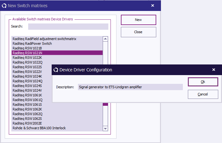
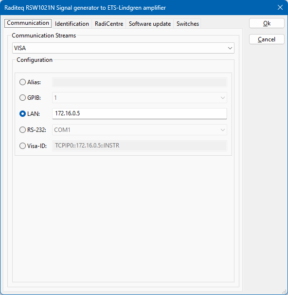
- Open the Advanced driver configuration and go to the Communication tab. Configure the correct communication settings to control the relay card, depending on how it is connected to the PC.
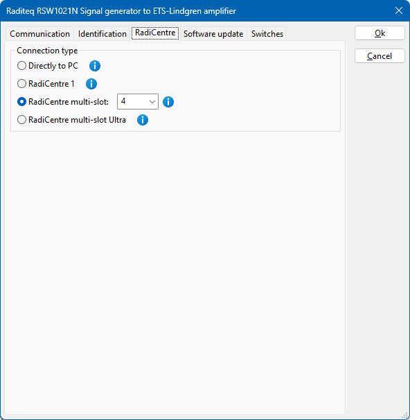
- For the Raditeq RSW1021N relay, also the RadiCentre slot number in which the card is present should be selected. Select the RadiCentre tab, and select the correct slot number, which is 4 for Relay A in the example setup.
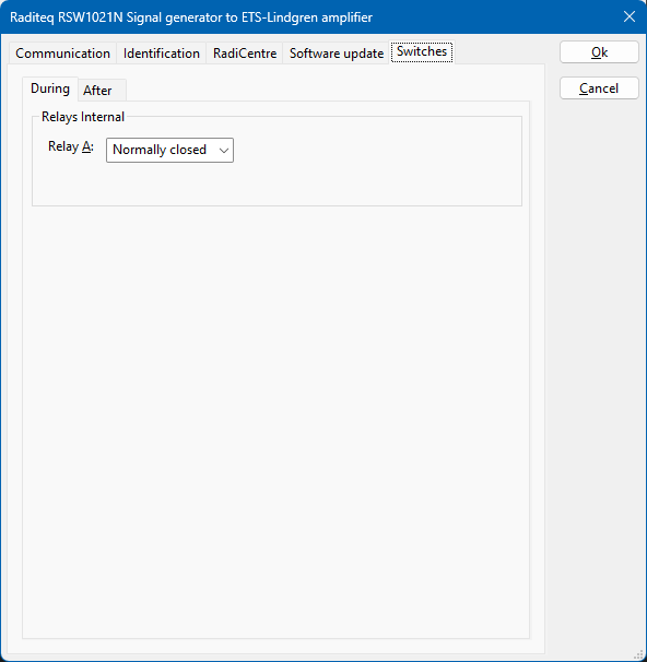
- Select the Switches tab and select Normally Closed for the relay in the During phase. The relay position that is selected on the During tab is the relay position that is active 'during' the test. The relay position that is selected on the After tab is the relay position that is active 'after' the test is finished.
- Close the advanced driver configuration.


Repeat the above steps to also create drivers for all the other signal paths of Relay A, Relay B and Relay C:
| Relay | device driver name | RadiCentre slot number | internal relay state |
|---|---|---|---|
| Relay A | Signal generator to ETS-Lindgren amplifier | 4 | Normally closed |
| Relay A | Signal generator to Bonn amplifier | 4 | Normally open |
| Relay B | ETS-Lindgren amplifier to forward power meter | 5 | Normally closed |
| Relay B | Bonn amplifier to forward power meter | 5 | Normally open |
| Relay C | ETS-Lindgren amplifier to reflected power meter | 6 | Normally closed |
| Relay C | Bonn amplifier to reflected power meter | 6 | Normally open |
After these switch matrix device drivers are created, the list of configured device drivers is available as:

Selecting the switch matrix device drivers in the test site[edit]
Once all the device drivers for the switch matrix states and the other test and measurement equipment are created, those device drivers can be selected in the corresponding test site configuration. In the provided example, two test sites are being used, each having their own operational frequency range.
- Open the test site configuration by selecting from the menu
- Configuration
- Test Equipment
-
-
- Click on Add to make a new test site, and specify the name of the new test site: "Radiated Immunity - 80 MHz - 1 GHz"
- Now Add all the device drivers for this test site, needed to perform the test. In this example that would be:
- Signal generator: RadiGen RGN2006B
- Amplifier: ETS-Lindgren 8100-002
- Coupler: Bonn BDC 0110-40
- Forward power meter: RadiPower RPR2006C (Fwd)
- Reflected power meter: RadiPower RPR2006C (Refl)
- Antenna: Schwarzbeck VULB 9160
- Also add the previously created switch-matrix device drivers. More than 1 switch matrix device driver can be selected in the test site configuration:
- Switch matrix: Signal generator to ETS-Lindgren amplifier
- Switch matrix: ETS-Lindgren amplifier to forward power meter
- Switch matrix: ETS-Lindgren amplifier to reflected power meter
- Close the test site configuration, by clicking on Save and Close
The test site configuration is now thus available as:

Similarly, the test site configuration for "Radiated Immunity - 1 GHz - 3 GHz" can be created, with all the relevant device drivers, and switch matrix device drivers that are applicable for the high frequency range. That test site configuration will then be available as:

Conclusion[edit]
By using one or more switch matrix device drivers, it is possible to create fully automated control of the relay switching when the RadiMation® test is started. This example shows how this can be implemented for a low frequency signal path and a high frequency signal path in a Radiated Immunity test. The same technique by creating switch matrix device drivers is also working in other tests like Conducted Emission, and all the other RadiMation® modules.