RadiMation Application Note 157: Difference between revisions
No edit summary |
|||
| Line 6: | Line 6: | ||
The exact requirements and test methods for the RS103 are specified in the [[MIL-STD-461]]. | The exact requirements and test methods for the RS103 are specified in the [[MIL-STD-461]]. | ||
This application note demonstrates how to setup a closed loop test. When testing closed loop, no calibration is required. | |||
== Necessary equipment == | == Necessary equipment == | ||
Revision as of 11:32, 29 August 2024
How to perform a MIL-STD-461 RS103, radiated susceptibility, electric field[edit]
This application note explains how the MIL-STD-461 RS103, radiated susceptibility, electric field test can be performed with RadiMation®
RS103 is a test method used in military and aerospace environments to evaluate the susceptibility of electronic equipment to radiated electromagnetic fields across a frequency range of 2 MHz to 40 GHz. It primarily uses pulse modulation to simulate high-intensity electromagnetic interference, ensuring that devices can withstand these conditions without malfunctioning.
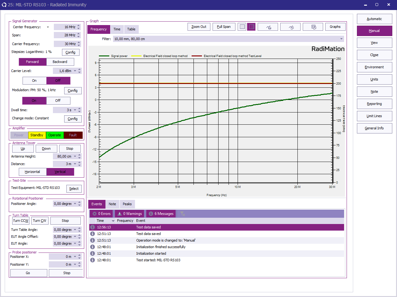
The exact requirements and test methods for the RS103 are specified in the MIL-STD-461. This application note demonstrates how to setup a closed loop test. When testing closed loop, no calibration is required.
Necessary equipment[edit]
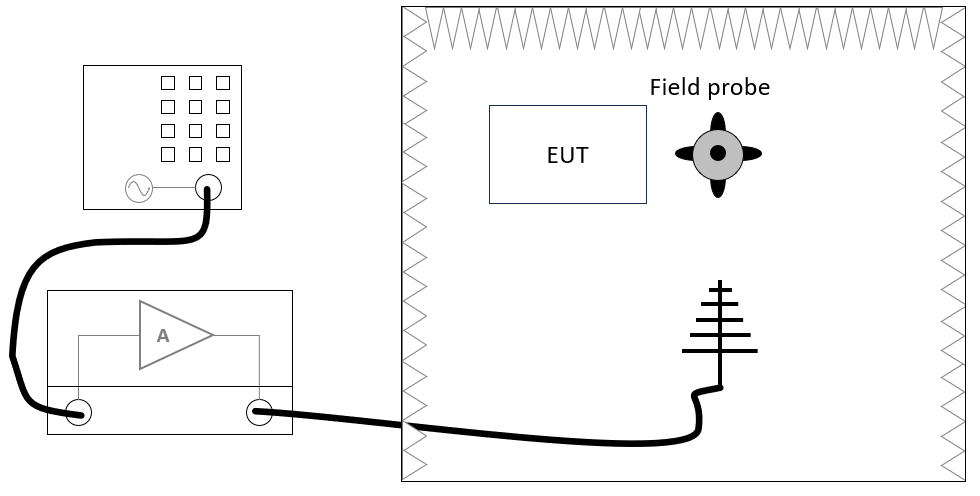
The following devices are necessary to perform the RS103 test:
- Signal generator
- Amplifier
- Antenna
- Field probe
Define the test level[edit]
If the limit in "Table XI RS103" is the same value for the whole frequency range the creation and usage of the correction file can be skipped. Usage of the correction file is only applicable to variable limits.
Create a correction file for the test level[edit]
-
 File
File
-
 New
New
-
 Correction
-
-
-
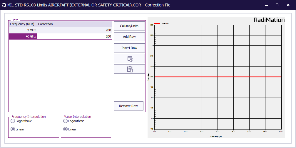
First create a correction file in RadiMation® and specify the test level (See 'Table XI RS103 limits.').
-
 File
File
-
 Save correction
-
-
Store the correction file with the RS103 limits as file on disk.
This correction file with the test level will be used during EUT testing.
EUT Testing[edit]
EUT Testing equipment[edit]
The configuration of the EUT test site should contain the following devices:
| # | Device name | Tab in testsite configuration window | note |
|---|---|---|---|
| Signal Generator | Devices 1 | The signal generator to use | |
| Amplifier | Devices 1 | The amplifier to use | |
| Antenna | Devices 1 | The antenna to use | |
| Field Sensor 1 | Field probes | The field sensor to use |
Configure the EUT test[edit]
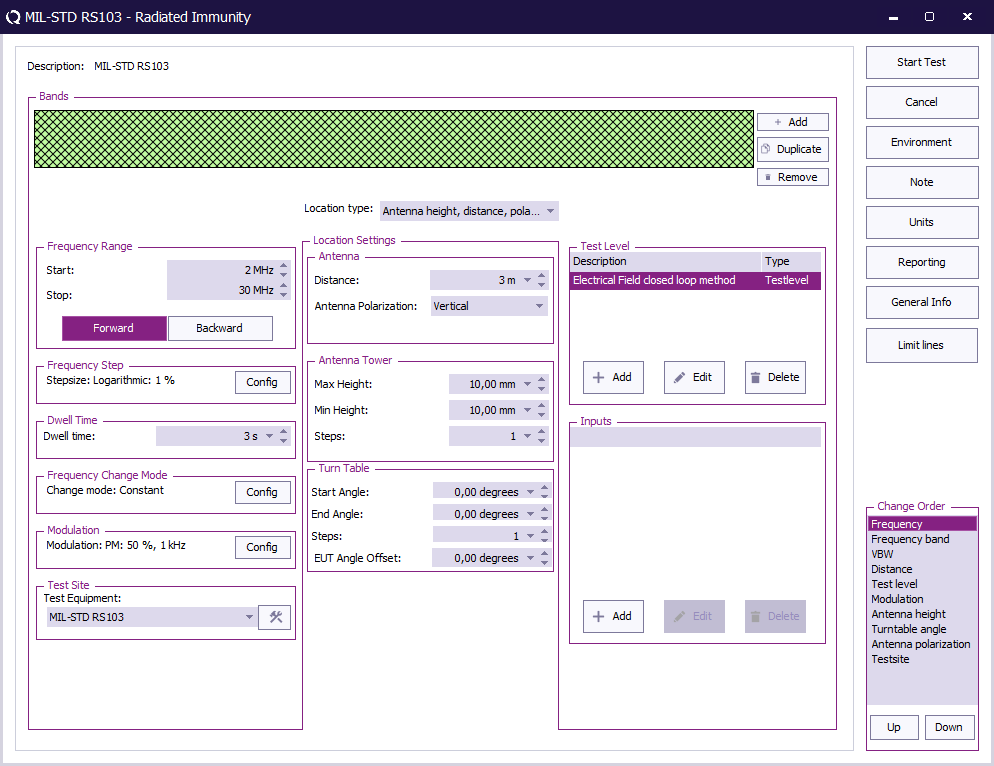
To perform the test on the EUT, create a radiated immunity multiband test.
Create a test setup configuration file for the following settings:
| Frequency range | Frequency step | Polarization |
|---|---|---|
| 2 MHz to 30 MHz | 1% | Vertical |
| 30 MHz - 18 GHz | 0.5% | Both (Horizontal and vertical) |
| 18 GHz - 40 GHz | 0.25% | Both (Horizontal and vertical) |
The radiated immunity multiband test, can be configured by selecting from the menu:
-
 Tests
Tests
-
 Radiated Immunity
-
 Multiband
-
 New
New
-
-
-
-
| The start frequency of the test. For example 2 MHz. |
| The stop frequency of the test. For example 30 MHz. |
| The frequency step, for the applicable steps see "Table III susceptibility scanning" in MIL-STD-461G. |
| The dwell time. |
| Constant. |
| The modulation to use see below. |
| The equipment needed for the radiated susceptibility test. |
| Antenna height, distance, polarization and angle. |
| Specify the Electrical field closed loop method test level and configure a Constant field or Variable field |
| No inputs are needed. |
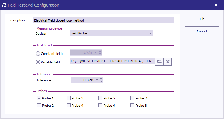
At TestLevel click Add to add a new Test level and select TestLevel - Electrical field closed loop method
| The description of the test level. |
| Check Variable field and specify the correction file for the applicable test level. When the level is one fixed value check Constant field and specify the test level |
| Specify the tolerance to use. |
| Check Probe 1 to measure with the first probe. |
To configure the pulse modulation settings click Config next to the modulation settings, click the PM tab, and enter the pulse modulation settings as defined in 5.21.3.4.c.1.a
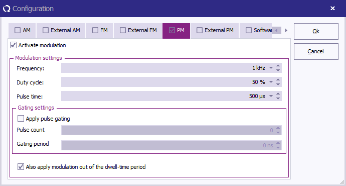
| Check this checkbox to enable the pulse modulation. |
| The PM frequency 1 kHz. |
| A duty cycle of 50%. |
| Check this checkbox to enable modulation outside the dwell-time. |
When all settings are configured press Start Test to run the test.
EUT test result[edit]
Once the test is finished, the results of this test are stored in the EUT file and available as one of the performed Tests in the EUT file. Selecting the corresponding test result and pressing on Info will show the test results again.
Conclusion[edit]
The RadiMation® Radiated Immunity multiband test can be used to perform the RS103 EUT test.
