Multiband-radiated-immunity-testlevels: Difference between revisions
No edit summary |
No edit summary |
||
| Line 4: | Line 4: | ||
{{:Testlevel power input}} | {{:Testlevel power input}} | ||
{{:Testlevel | |||
{{:Testlevel VSWR}} | |||
Revision as of 11:31, 11 November 2024
Test levels[edit]
In RadiMation’s MultiBand testing modules, "test levels" are settings that control how power is regulated, limited, and measured during EMC testing. They play a crucial role in ensuring that devices under test are exposed to consistent and precise levels across multiple frequency bands. Here’s how test levels work and how they affect your testing process in RadiMation:
Types of Test Levels[edit]
In RadiMation’s MultiBand modules, there are different types of test levels that each serve a unique purpose during testing:
- Power Leveling (Test Level): This type of test level sets the target power level that the test equipment should aim to achieve. It ensures that a specific level of electromagnetic energy is consistently applied to the device under test.
- Power Limitation (Limit Level): This is used to cap the maximum power level that the system can apply. By setting limit levels, you ensure that the power applied never exceeds safe or specified levels, helping to protect the device under test from overexposure.
- Measurement Inputs (Input Level): Input levels define what measurements are necessary during the test. For instance, they can specify particular signals or parameters that the system should measure at specific points during the test, allowing you to monitor the test environment and the device's behavior closely.
How Test Levels Are Applied[edit]
Test levels in RadiMation can be configured to suit the specifics of your testing requirements. Each test level can have its own configuration, and the RadiMation software allows you to select and adjust these levels within the test module’s interface. For example, you can set different test levels for different frequency bands, helping to simulate various conditions that the device might encounter.
When setting up a test in a MultiBand module, you’ll be able to choose a test level from RadiMation’s built-in list of available test levels for a given module. Once a test level is selected, the system will:
- Regulate Power: If you selected a power leveling type, the system will continuously adjust to maintain the specified power level during the test.
- Enforce Limits: If you set a limit level, RadiMation will prevent the power from exceeding this limit, which can be especially useful when testing devices with sensitive components.
- Measure Inputs: For input levels, the system will capture and log the specified measurement data. This data will come available in the test data and can be used for furthet visualization and reporting.
RadiMation’s MultiBand modules also allow you to set up multiple test levels for a single test. This flexibility enables you to create complex testing scenarios. Test levels in RadiMation’s MultiBand modules are essential settings for regulating, limiting, and measuring the levels too which the devices under test are submitted. By configuring these levels appropriately, you can ensure accurate and effective testing outcomes.
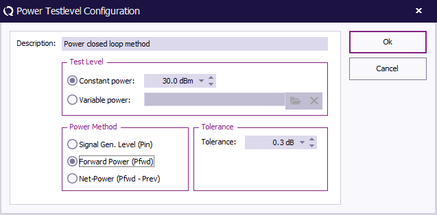
Test level: Power closed loop method[edit]
| A field to enter a description for the power test level method being configured. |
| A test level option where the power is kept constant at a specified level, in this case, -100.0 dBm. |
| An option to set a range or variable power level for testing. This option is disabled in the image. |
| A power method that uses the signal generator level (Pin) as the reference for power measurement. |
| A power method that uses the forward power (Pfwd) as the reference for power measurement. |
| A power method that calculates net power by subtracting the previous power level (Prev) from the forward power (Pfwd). |
| A field to set a tolerance level for power measurement in dB, which defines the acceptable variation range. |
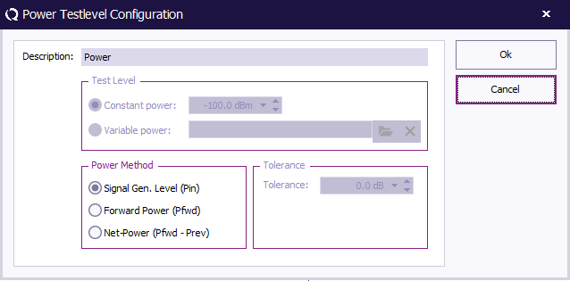
Input: Power[edit]
| A field to enter a description for the power test level method being configured. |
| A test level option where the power is kept constant at a specified level, in this case, -100.0 dBm. |
| An option to set a range or variable power level for testing. This option is disabled in the image. |
| A power method that uses the signal generator level (Pin) as the reference for power measurement. |
| A power method that uses the forward power (Pfwd) as the reference for power measurement. |
| A power method that calculates net power by subtracting the previous power level (Prev) from the forward power (Pfwd). |
| A field to set a tolerance level for power measurement in dB, which defines the acceptable variation range. |
Input Test level: VSWR[edit]
-
 Description The description of the input.
-
Calculation[edit]
The VSWR (Voltage Standing Wave Ratio) test level in RadiMation is a measurement that indicates how well the energy from a signal source is being transferred to a device under test. It provides insight into the efficiency of power delivery, with a lower VSWR indicating better efficiency and minimal energy reflection. This is important in electromagnetic immunity testing to ensure accurate power application across test frequencies.
In RadiMation, the VSWR is calculated based on the Return Loss (RL) between the forward power and reflected power.
- Calculate Return Loss (RL):
In RadiMation, this is calculated as the difference between the forward power and the reflected power.
- Calculate the Reflection Coefficient:
The reflection coefficient is a value derived from the Return Loss. It quantifies the proportion of energy reflected from the device.
- Calculate VSWR:
If the reflection coefficient is 1 (meaning full reflection with no power transfer), the VSWR is set to a high value (e.g., 1000) to represent an infinite VSWR. VSWR measures the standing wave pattern created by the interference between the forward and reflected waves. It’s calculated based on the reflection coefficient as follows:


