Signal Offset With Receiver: Difference between revisions
No edit summary |
|||
| Line 35: | Line 35: | ||
==A possible cause== | ==A possible cause== | ||
A possible cause for this is that the 10 MHz references are not the same. To check this connect the external reference output from the receiver to the external reference input of the signal generator. | A possible cause for this is that the 10 MHz references are not the same. To check this connect the external reference output from the receiver to the external reference input of the signal generator. You can also connect this the other way around, but in many cases the 10 MHz from the receiver will be more accurate then the one of the signal generator. Because the references are now the same the frequency will be more accurate, this will be in orders of Hz. Because the measurement is done with a 200 Hz RBW and step size this may just be the accurate we need to detect a peak at 100 kHz. | ||
==Example connectors== | ==Example connectors== | ||
Revision as of 12:33, 20 December 2007
this document is describing a possible solution for the frequency offset when doing a measurement with signal generator and receiver.
| Receiver Settings | |
|---|---|
| Start Frequency | 30 kHz |
| End Frequency | 150 kHz |
| RBW | 200 Hz |
| Step size | 200 Hz |
Note: The step frequency of 200 Hz is taken increase the impact, to get the right frequency use RBW/2 or less as step frequency.
| Signal Generator Settings | |
|---|---|
| Carrier Frequency | 100 kHz |
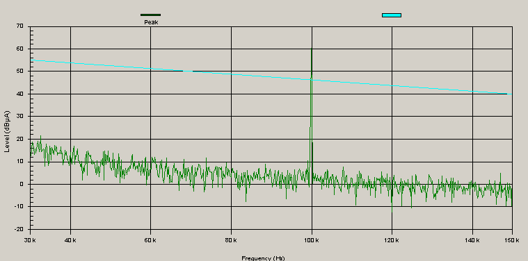
With these settings we get the following emission spectrum:

As you can see the emission is starting a little bit before the 100 kHz.
A possible cause[edit]
A possible cause for this is that the 10 MHz references are not the same. To check this connect the external reference output from the receiver to the external reference input of the signal generator. You can also connect this the other way around, but in many cases the 10 MHz from the receiver will be more accurate then the one of the signal generator. Because the references are now the same the frequency will be more accurate, this will be in orders of Hz. Because the measurement is done with a 200 Hz RBW and step size this may just be the accurate we need to detect a peak at 100 kHz.
Example connectors[edit]
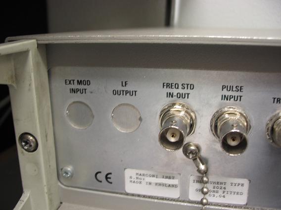
Marconi 2024 Reference connector
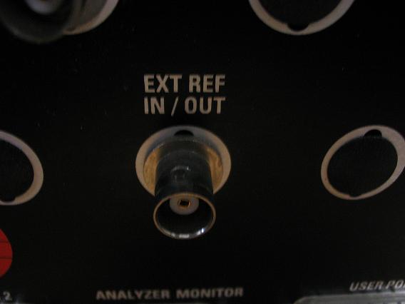
R & S Esi 40 Reference connector

