RadiMation Application Note 145: Difference between revisions
Jump to navigation
Jump to search
No edit summary |
|||
| Line 1: | Line 1: | ||
== How to perform a MIL-STD RE102 Radiated emission test == | == How to perform a MIL-STD RE102 Radiated emission test == | ||
This application note explains how the MIL-STD RE102 Radiated Emission test can be performed with {{RadiMation}}. | This application note explains how the MIL-STD RE102 Radiated Emission test can be performed with {{RadiMation}}. | ||
The RE102 test is described in the [ | The RE102 test is described in the [[MIL-STD-461]]. | ||
== Equipment used == | == Equipment used == | ||
Revision as of 13:10, 2 September 2022
How to perform a MIL-STD RE102 Radiated emission test[edit]
This application note explains how the MIL-STD RE102 Radiated Emission test can be performed with RadiMation®. The RE102 test is described in the MIL-STD-461.
Equipment used[edit]
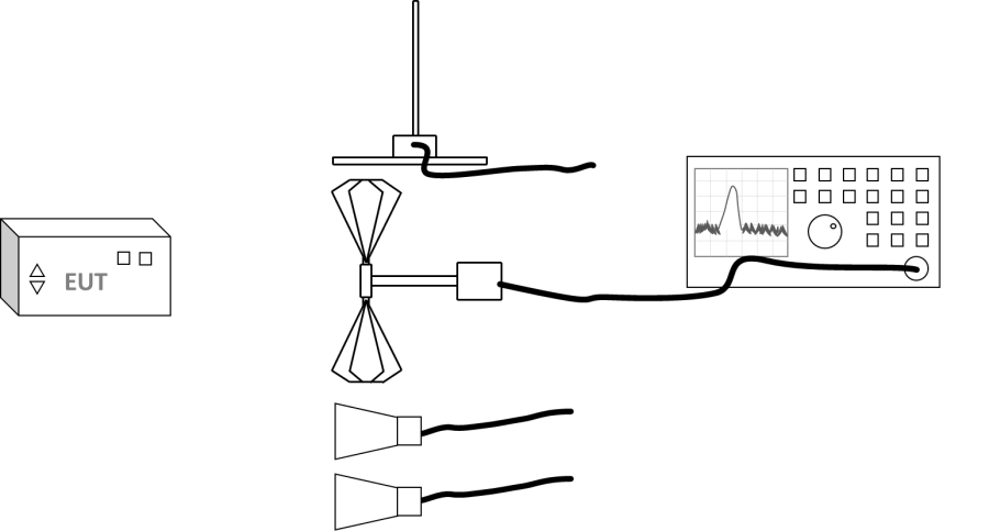
For this test four antennas are used.
| Antenna | Frequency range |
|---|---|
| Rod antenna | 10 kHz to 30 MHz |
| Biconical antenna | 30 MHz to 200 MHz |
| Double ridge horn | 200 MHz to 1 GHz |
| Double ridge horn | 1 GHz to 18 GHz |
The following devices should be configured:
- Receiver
- 4 Antennas
- Cables
Optionally[edit]
- Antenna polarizer / tower, above 30 MHz both vertical and horizontal polarizations should be measured.
Configuration of the test sites[edit]
Create a test site for each antenna / frequency range:
| Device name | Tab in testsite configuration window | note |
|---|---|---|
| Antenna | Devices 1 | Antenna for the required frequency range |
| Antenna tower | Devices 1 | Optional antenna tower |
| Spectrum Analyser | Devices 2 | The receiver used for the test |
| Cable preamp -> analyser | Cables | Cable with a correction file specified for the loss |
Perform the test[edit]
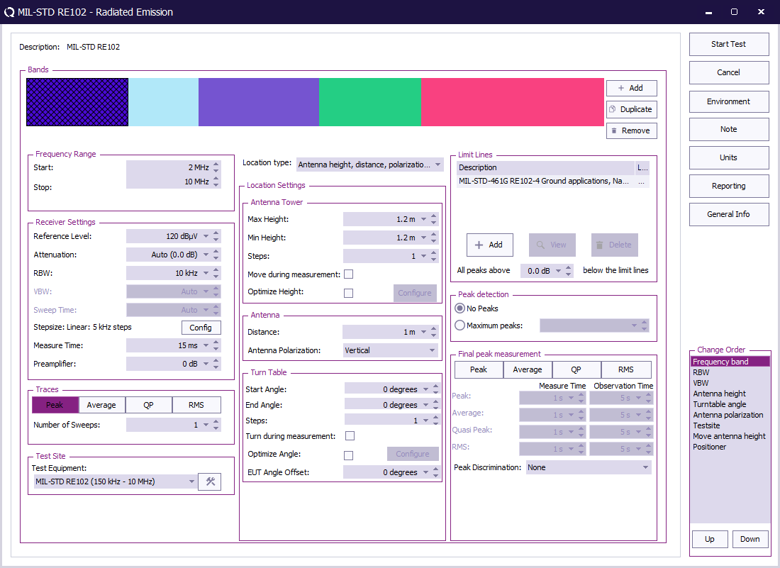
To perform the test start a Radiated Emission Multiband test:
-
 Tests
Tests
-
 Radiated Emission
-
 Multiband
-
-
-
| The start frequency of the test. For example 10 kHz. |
| The stop frequency of the test. For example 150 kHz. |
| The reference level set in an analyser, not used in a receiver |
| The attenuation set in the receiver |
| The RBW set in the receiver |
| The step size set in the receiver |
| The measure time set in the receiver |
| The preamplifier setting set in the receiver |
| The type of trace set in the receiver |
| The equipment used for the measurement |
| Set this to Antenna height, distance, polararization and angle |
| The max height for the antenna tower |
| The min height for the antenna tower |
| The number of height positions to measure |
| If the antenna tower can move during the measurement |
| Find the optimal emission around a certain height |
| The used antenna distance |
| Which polarization is used, Vertical, Horizontal or both |
| The min turn table angle` |
| The max turn table angle |
| The number of angles to measure |
| If the turn table can move during the measurement |
| Find the optimal emission around a certain angle |
| The offset of the EUT on the table |
| The applicable limit lines can be added |
| No peaks should be measured in RE102 |
| No peaks should be measured for RE102 |
| No final peak measurement is needed for RE102 |
When all parameters are configured for the RE102 test, press Start Test to perform the measurement.
Repeat the test for each point to test.

