File:ApplicationNote123Switches.png: Difference between revisions
Jump to navigation
Jump to search
No edit summary |
(Joro uploaded a new version of File:ApplicationNote123Switches.png) |
(No difference)
| |
Latest revision as of 15:35, 3 November 2025
A schematic diagram of using a low frequency and high frequency amplifier, coupler and antennas, including the switches to automate two frquency ranges.
This diagram is used in RadiMation Application Note 123, which explains how switch matrixes can be configured in RadiMation®
File history
Click on a date/time to view the file as it appeared at that time.
| Date/Time | Thumbnail | Dimensions | User | Comment | |
|---|---|---|---|---|---|
| current | 15:35, 3 November 2025 | 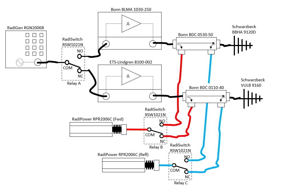 | 1,009 × 671 (77 KB) | Joro (talk | contribs) | Updated diagram, also including the names of the devices |
| 12:56, 3 November 2025 | 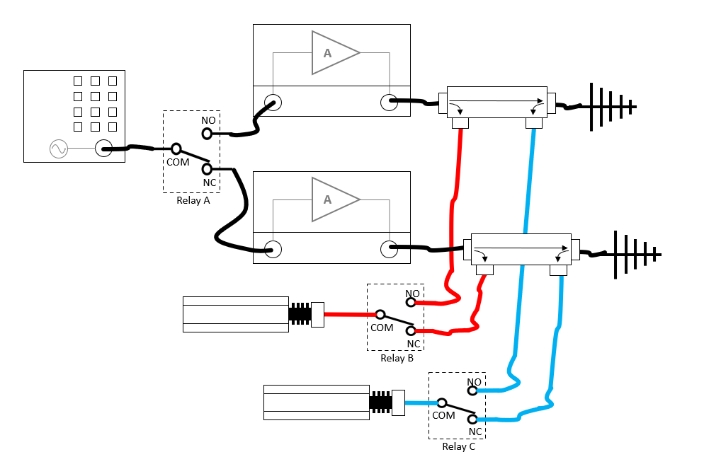 | 994 × 663 (47 KB) | Joro (talk | contribs) | Updated switch diagram, using the often used RadiMation equipment drawings | |
| 15:17, 7 June 2019 | 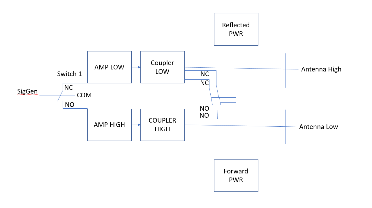 | 1,277 × 716 (27 KB) | Tjsc (talk | contribs) |
You cannot overwrite this file.
File usage
The following page uses this file: