RadiMation Application Note 111: Difference between revisions
No edit summary |
No edit summary |
||
| Line 6: | Line 6: | ||
== Hardware setup. == | == Hardware setup. == | ||
The rf switch card in the RadiCentre has an interlock input which must be connected to all safety switches (doors etc). | The rf switch card in the RadiCentre has an interlock input which must be connected to all safety switches (doors etc). | ||
Typically the "A" relay is switched to NC | Typically the "A" relay is switched to NC when the interlock is not closed. | ||
In the case the interlock is not closed, {{Radimation}} will not start a test and lasers will be switched off. | |||
=== Schematic overview of interlock relay. === | === Schematic overview of interlock relay. === | ||
Revision as of 10:05, 25 February 2019
How to use the RadiCentre® safety interlock system in RadiMation®[edit]
| Warning: | This page is a draft |
This application note describes how RadiMation® can be configured to make optimal use of the safety interlock system that is available on the RadiCentre®.
Hardware setup.[edit]
The rf switch card in the RadiCentre has an interlock input which must be connected to all safety switches (doors etc). Typically the "A" relay is switched to NC when the interlock is not closed. In the case the interlock is not closed, RadiMation® will not start a test and lasers will be switched off.
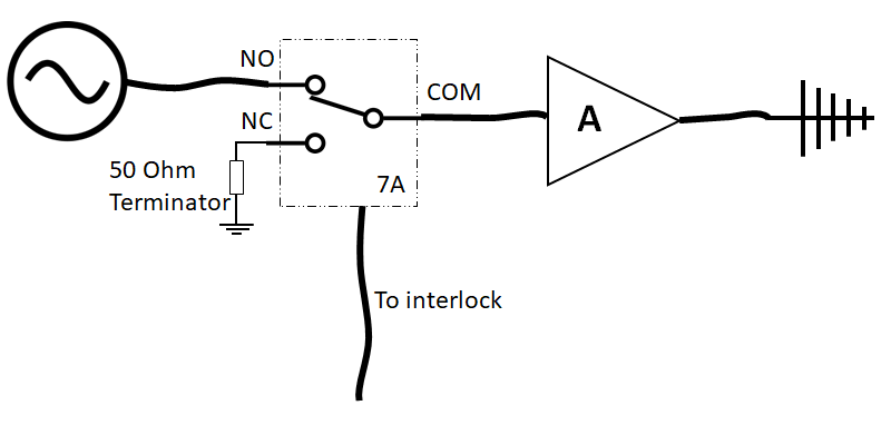
Schematic overview of interlock relay.[edit]
In this schema we can see that we are using 7A, 7 for the 7th slot in RadiMation® and A for the relay.
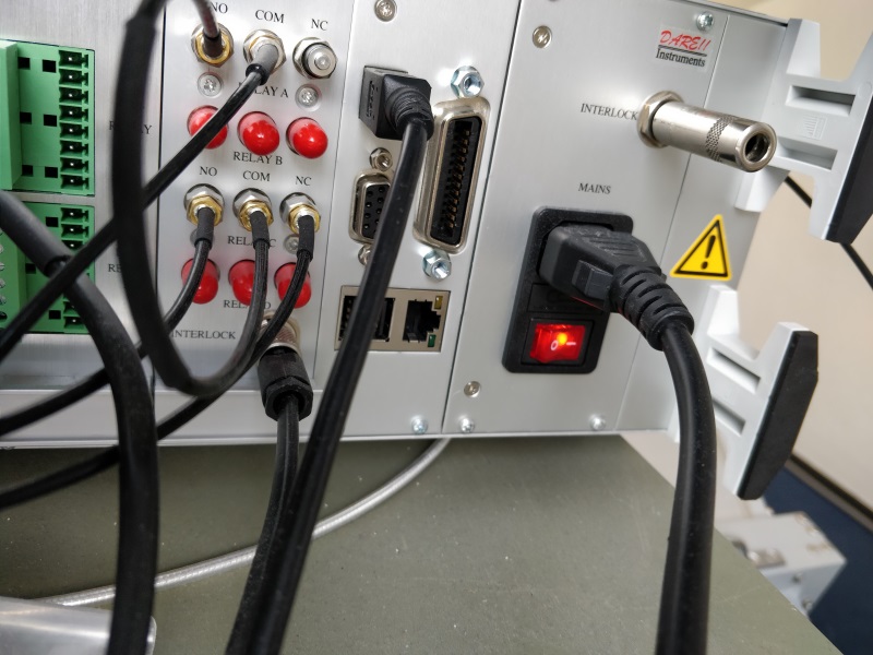
Picture of the backside of the RadiCentre:
Configure RadiMation.[edit]
In this example we are going to configure a RSW1024S switch card.
Open RadiMation® Open the menu:
-
 Test-sites
-
 Configure...
-
-
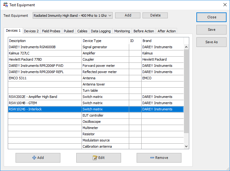
At test equipment select the applicable test-site. Right click switch matrix and select the driver used for switching the interlock. In this example we use "RSW1024S - Interlock" to switch the "A" relay.
Driver configuration[edit]
After adding the driver to the testsite we are going to configure the switches.
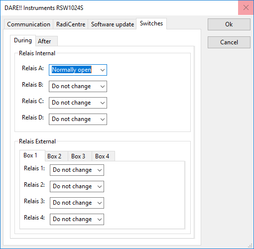
- Double click the driver to configure it
- Select Advanced
- Select the tab Switches
- Configure on the “During” tab relay A to “Normally open”
- Configure on the “After” tab, Relay A to “Normally closed”


