Talk:RadiMation Application Note 106: Difference between revisions
Jump to navigation
Jump to search
No edit summary |
(→Image) |
||
| Line 18: | Line 18: | ||
== Image == | == Image == | ||
An image seems to be present that shows a changing input, and the measured values. | An image seems to be present that shows a changing input, and the measured values. | ||
See: [[File:MeasureLoop.png]] | |||
See: | |||
[[File:MeasureLoop.png]] | |||
However that file is not used in this applicatin note. | However that file is not used in this applicatin note. | ||
Latest revision as of 13:16, 27 October 2020
Goal
To explain how the parameters of the powermeter configuration can be used to retrieve stable powermeter readings
Todo
- V Include a screenshot of the powermeter parameter settings
- V Explain the purpose of the possible parameters
- V Explain the different between levelling and monitoring
- V Explain tips and tricks on how to determine better measurement parameters
- V Explain that the change is caused by the slowness of the powermeter but also by the slowness of the signal generator
- ? Include a picture of the Marconi power change when the carrier is changed, measured using the radipower envelope mode.
- V * Do a levelling test. Signal generator carrier going up and down a lot? => Too fast. Slow it down
- V * Slow measurements => Make it faster, but check (see at previous point) that it is not too fast
- * Use the device specific input measurement to get 'internal' information of the levelling measurement in the powermeter
discussion
- Should we also handle the same information for the fieldstrength sensor in the same application note, or should we create a separate application note for almost the same information for the fieldstrength sensor?
Image
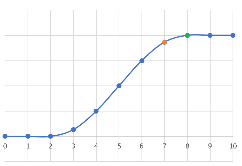
An image seems to be present that shows a changing input, and the measured values.
See:
However that file is not used in this applicatin note.
