LeCroy LT Series: Difference between revisions
No edit summary |
DevicesBot (talk | contribs) (Updated DeviceDriverInfo template) |
||
| Line 4: | Line 4: | ||
|DeviceDriverName=LECROYLT | |DeviceDriverName=LECROYLT | ||
|DeviceType=LT Series | |DeviceType=LT Series | ||
|HideAutoData=1 | |||
|SupportedDeviceTypes=64 | |SupportedDeviceTypes=64 | ||
}} | }} | ||
{{:LeCroyOscilloscopeDeviceDriverConfiguration}} | {{:LeCroyOscilloscopeDeviceDriverConfiguration}} | ||
Latest revision as of 01:03, 21 April 2021
The LeCroy LT Series device driver is a AD Converter which is supported by RadiMation®.
The following tabs are available in the advanced configuration of the LeCroy LT Series:
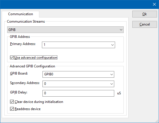
On the Communication tab, the desired communication method can be selected and configured. Depending on the selected method, additional relevant settings are shown and can be configured.
| Selects the medium or method that should be used to communicate with the device. Depending on the capabilities of the device this can be one or more of:
See the Communication Settings in Chapter 15, on how to configure each of these methods. |
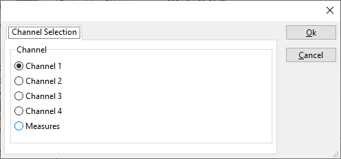
On the Channel Selection tab, the desired channel that should be measured can be selected.
| Channel 1 will be used as the measurement input. |
| Channel 2 will be used as the measurement input. |
| Channel 3 will be used as the measurement input. |
| Channel 4 will be used as the measurement input. |
| The 'Measures' as they can be configured on the LeCroy oscilloscope will be used. |
Some LeCroy oscilloscope devices only have 2 input channels, and in that case the configuration dialog will only show the channels that are supported.
Channel[edit]
If one of the Channel options is selected, the EUT Monitoring device in RadiMation® will use the following mapping:
| Channel | Measurement | Maximum value |
|---|---|---|
| 1 | Minimum amplitude | 353.55 V |
| 2 | Maximum amplitude | 353.55 V |
| 3 | Amplitude | 353.55 V |
| 4 | Peak to Peak voltage | 707.1 V |
| 5 | RMS value | 250 V |
| 6 | Frequency in MHz | 200 MHz |
| 7 | Dutycycle | 100 % |
| 8 | Trace dump |
The 'Trace dump' mode retrieves the trace data of the selected channel, and then creates a DUMP_<FREQ>MHz_<YEAR>-<MONTH>-<DAY>_<HOUR>-<MINUTE>-<SEC>.CSV file in the C:\Work\ directory that contains the raw data of the complete trace. The graph in RadiMation® thus doesn't show any logical information, however all the raw data of the traces is present in several files in the C:\Work\ directory.
Measures[edit]
If the Measures options is selected, the EUT Monitoring device in RadiMation® is retrieving the values from the 'Measure' that are configured in the LeCroy oscilloscope itself. The to be measured value can thus be configured in the LeCroy by using one of the available measurement functions. See the end-user manual of the LeCroy on how these 'Measures' can be configured. The measure configuration in the LeCroy also includes from which input channel the value should be measured. These measures are numbered in the LeCroy, and the same numbering is used in the RadiMation®. The EUT Monitoring channel 2 will thus use the value of Measure 2 in the LeCroy.

