RadiMation Application Note 141: Difference between revisions
(Created page with "__NOTOC__ = How to create and apply a cable correction = This {{RadiMation}} application note explains how to create a cable correction and apply it in {{RadiMation}}. When us...") |
No edit summary |
||
| Line 47: | Line 47: | ||
[[Image:AddCableTestEquipment.png]] | [[Image:AddCableTestEquipment.png]] | ||
[[Category:Application Note]] | |||
Revision as of 14:23, 16 March 2023
How to create and apply a cable correction[edit]
This RadiMation® application note explains how to create a cable correction and apply it in RadiMation®. When using cables for example in emission measurements or using attenuators in a conducted immunity calibration setup it is possible to compensate the losses or gain in RadiMation®. This way RadiMation® is showing correct measurement values.
This procedure consist of 3 steps:
- Create a calibration file.
- Create a Cable device driver and apply the correction file.
- Add the cable to the test equipment.
Create a calibration file[edit]
There are two methods to create a correction file:
Measure attenuation or gain[edit]
It is possible to use the attenuation gain measurement to automatically create a correction and measure the cable or attenuator with a signal generator and a power meter or spectrum analyser.
this is described here: Attenuation / Gain System Calibration
Create a correction manually[edit]
To create a correction file manually, create a new correction file:
-
 File
File
-
 New
New
-
 Correction
-
-
-
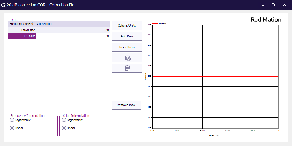
Click insert row to add a second row and set the start and stop frequency with the corresponding attenuation values.
And save the correction to a file
-
 File
File
-
 Save correction as...
-
-
It is also possible to paste data from for example Excel with the 5th button (paste data from clipboard). Make sure the data is in MHz and correction in dB. This feature is particularly used when correction values are supplied with a device or created with other software.
Create a cable device driver[edit]
-
 Devices
-
 Devices
-
 Cables
-
 Add Cables...
-
-
-
-
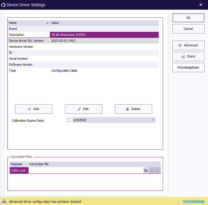
- Choose configurable cable and click 'New'
- Enter a description for the cable or attenuator
- Below at Correction files select the applicable correction file.
- Click "Ok" to close the window.
Add the cable to the test equipment[edit]
To apply the cable, open test equipment:
-
 Test-sites
-
 Configure
-
-
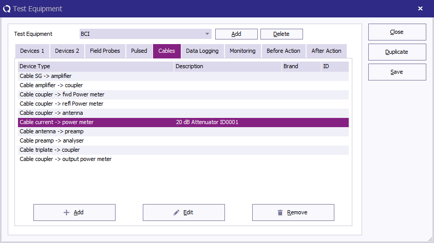
- At the pull down menu select the applicable test equipment, or if needed create a new one.
- Select the 5th tab called "Cables"
- Click the button "Add" and add the cable to the applicable path.


