RadiMation Application Note 157: Difference between revisions
| Line 46: | Line 46: | ||
Create a test setup configuration file for the following frequency ranges: | Create a test setup configuration file for the following frequency ranges: | ||
{|class="wikitable" | {|class="wikitable" | ||
! Frequency range || Polarization | ! Frequency range || Frequency step ||Polarization | ||
|- | |- | ||
| 2 MHz to 30 MHz || Vertical | | 2 MHz to 30 MHz || 1% || Vertical | ||
|- | |- | ||
| 30 MHz - 18 GHz || Both (Horizontal and vertical) | | 30 MHz - 18 GHz || 0.5% || Both (Horizontal and vertical) | ||
|- | |- | ||
| 18 GHz - 40 GHz || Both (Horizontal and vertical) | | 18 GHz - 40 GHz || 0.25% || Both (Horizontal and vertical) | ||
|} | |} | ||
| Line 80: | Line 80: | ||
{{ScreenElementDescription|Tolerance|Specify the tolerance to use.}} | {{ScreenElementDescription|Tolerance|Specify the tolerance to use.}} | ||
{{ScreenElementDescription|Probes|Check Probe 1 to measure with the first probe.}} | {{ScreenElementDescription|Probes|Check Probe 1 to measure with the first probe.}} | ||
{{ScreenElementDescriptionEnd}} | |||
To configure the pulse modulation settings click {{ScreenElement|Config}} next to the modulation settings, click the {{ScreenElement|PM}} tab, and enter the pulse modulation settings as defined in 5.21.3.4.c.1.a | |||
[[File:RS103 Modulation settings.png]] | |||
{{ScreenElementDescriptionStart}} | |||
{{ScreenElementDescription|Activate modulation|Check this checkbox to enable the pulse modulation.}} | |||
{{ScreenElementDescription|Frequency|The PM frequency 1 kHz.}} | |||
{{ScreenElementDescription|Duty Cycle|A duty cycle of 50%.}} | |||
{{ScreenElementDescription|Also apply modulation out of the dwell-time period|Check this checkbox to enable modulation outside the dwell-time.}} | |||
{{ScreenElementDescriptionEnd}} | {{ScreenElementDescriptionEnd}} | ||
When all settings are configured press {{ScreenElement|Start Test}} to run the test. | When all settings are configured press {{ScreenElement|Start Test}} to run the test. | ||
Revision as of 16:00, 4 December 2023
How to perform a MIL-STD-461 RS103, radiated susceptibility, electric field[edit]
This application note explains how the MIL-STD-461 RS103, radiated susceptibility, electric field test can be performed with RadiMation®
The exact requirements and test methods for the RS103 are specified in the MIL-STD-461.
Necessary equipment[edit]
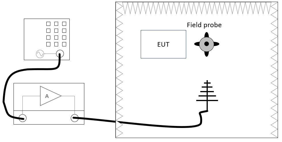
The following devices are necessary to perform the CS109 test:
- Signal generator
- Amplifier
- Antenna
- Field probe
Define the test level[edit]
Create a correction file for the test level[edit]
-
 File
File
-
 New
New
-
 Correction
-
-
-
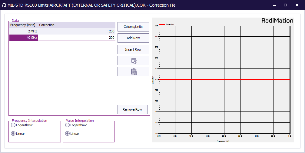
First create a correction file in RadiMation® and specify the test level (See 'Table XI RS103 limits.').
-
 File
File
-
 Save correction
-
-
Store the test level as correction file on disk.
This correction file with the test level will be used during EUT testing.
EUT Testing[edit]
EUT Testing equipment[edit]
The configuration of the eut test site should contain the following devices:
| # | Device name | Tab in testsite configuration window | note |
|---|---|---|---|
| Signal Generator | Devices 1 | The signal generator to use | |
| Amplifier | Devices 1 | The amplifier to use | |
| Field Sensor 1 | Field probes | The field sensor to use |
Configure the EUT test[edit]
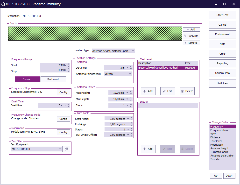
To perform the test on the EUT, create a radiated immunity multiband test.
Create a test setup configuration file for the following frequency ranges:
| Frequency range | Frequency step | Polarization |
|---|---|---|
| 2 MHz to 30 MHz | 1% | Vertical |
| 30 MHz - 18 GHz | 0.5% | Both (Horizontal and vertical) |
| 18 GHz - 40 GHz | 0.25% | Both (Horizontal and vertical) |
The radiated immunity multiband test, can be configured by selecting from the menu:
-
 Tests
Tests
-
 Radiated Immunity
-
 Multiband
-
-
-
| The start frequency of the test. For example 2 MHz. |
| The stop frequency of the test. For example 30 MHz. |
| The frequency step, see Table III. |
| The dwell time. |
| Constant. |
| The modulation to use see below. |
| The equipment needed for the radiated susceptibility test. |
| Antenna height, distance, polarization and angle. |
| Specify the Electrical field closed loop method test level. Also configured a "Variable field" |
| No inputs are needed. |
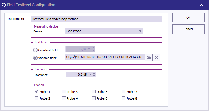
At TestLevel click Add to add a new Test level and select TestLevel - Electrical field closed loop method
| The description of the test level. |
| Variable field, and specify the correction file for the applicable test level. When the level is one value this value can be specified with Constant field |
| Specify the tolerance to use. |
| Check Probe 1 to measure with the first probe. |
To configure the pulse modulation settings click Config next to the modulation settings, click the PM tab, and enter the pulse modulation settings as defined in 5.21.3.4.c.1.a
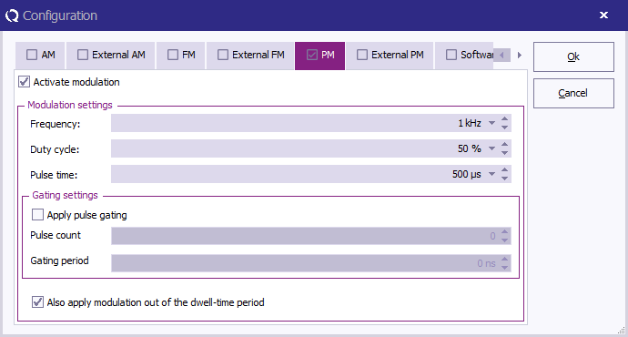
| Check this checkbox to enable the pulse modulation. |
| The PM frequency 1 kHz. |
| A duty cycle of 50%. |
| Check this checkbox to enable modulation outside the dwell-time. |
When all settings are configured press Start Test to run the test.
