RadiMation Application Note 135
How to program the RadiSense 10 calibration table
This RadiMation® application note explains how RadiMation® can be used to program the calibration data in a RadiSense 10 field probe.
The purpose of this application note is to explain how to program the calibration data into a RadiSense 10 field probe. This has the advantage that all the individual axis are corrected with their own calibration data in the probe itself. This will result in a more accurate measurement results.
It is also possible to correct the measurement data in RadiMation, instead of in the physical RadiSense field probe. See Application Note 153: Using Multi axis field corrections, on how this can configured.
| Note: | Any other correction file for the probe device driver settings should not be applied as well, as it will cause that a double correction is being applied to the measurement values! |
Creating the correction file
Create a new RadiMation correction file, by selecting from the menu:
-
 File
File
- New
- Correction .
-
-
-

Press Columns/Units to open the column selector. Then Add the Frequency, X-axis correction, Y-axis correction and Z-axis correction columns.

Paste the earlier determined correction values from Excel into the correction file.
| Note: | Multiple columns can be pasted from excel into a correction file with a single operation. If the first row in the table seen in the correction file is not overwritten, remove that first row using Remove Row. |

Then save the correction file to disk with a logical filename.
Uploading the correction file
- Go to the "advanced settings" of the RadiSense device driver and select User Calibration".
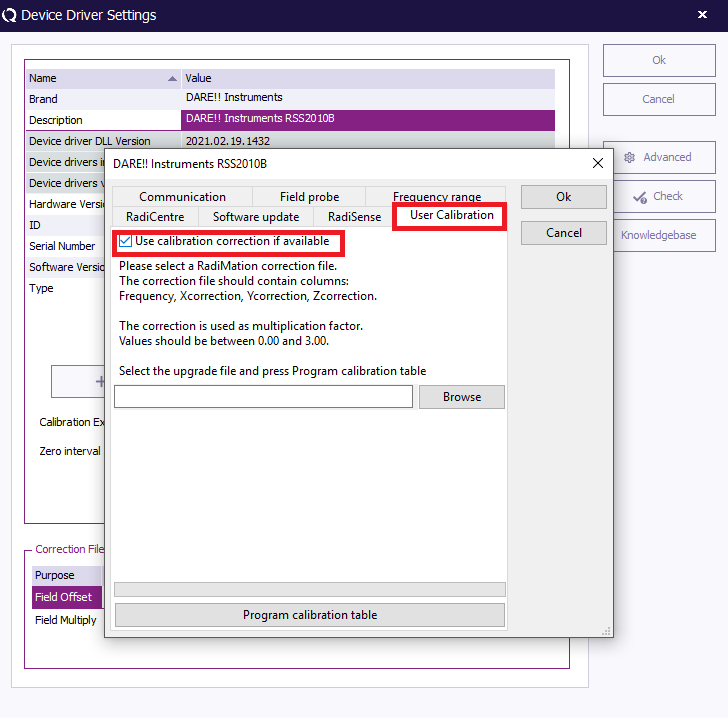
- Click Browse. Then find and select the earlier created correction file. Then click Program calibration table.
- When the progress bar is at 100% the programming has been succesfully completed.

Using the probe in a test
- Go to the "advanced settings" of the RadiSense device driver and select User Calibration".
- Make sure to check the checkbox “Use calibration if available” if the calibration should be used.
Conclusion
By following the steps that are explained in this RadiMation® application note, it is possible to program the calibration data into a RadiSense 10 field probe. This has the advantage that all the individual axis are corrected with their own calibration data in the probe itself. Also the isotropic field value is then optimally corrected, and will result in a more accurate measurement.