How to perform an IEC 61000-4-6, Conducted immunity test[edit]
This application note explains how the IEC 61000-4-6 conducted immunity test can be performed with RadiMation®.
The IEC 61000-4-6 conducted immunity test method is used for electrical and electronic equipment that may be subjected to radio-frequency disturbances conducted along cables coming from radio transmitters in the frequency range from 150 kHz up to 80 MHz. The exact requirements, calibration and EUT test methods are described in the IEC 61000-4-6 standard.
Necessary equipment[edit]
- Signal generator
- Amplifier
- Coupler
- Forward power meter
- Injection device
- Calibration jig
- Attenuator (optional)
- Sensor power meter
Calibration procedure[edit]
The calibration is performed to determine the power required to match the corresponding voltage test level seen at the output of the injection device.
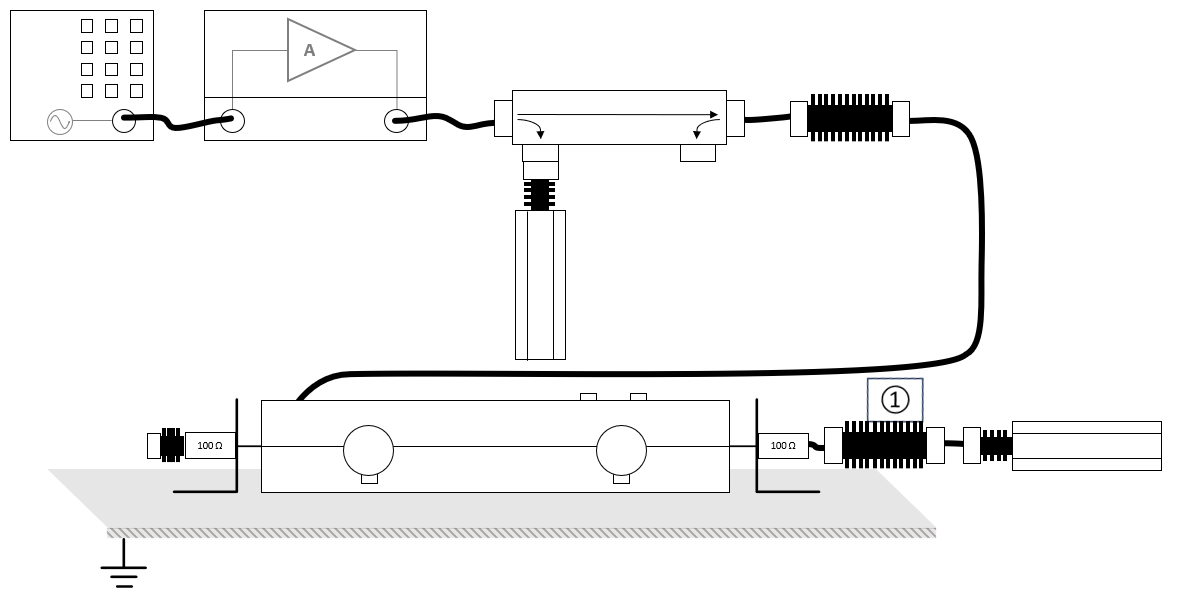
The configuration of the calibration test site should contain the following devices:
| # |
Device name |
Tab in testsite configuration window |
note
|
|
Signal Generator |
Devices 1 |
The signal generator to use
|
|
Amplifier |
Devices 1 |
The amplifier to use
|
|
Coupler |
Devices 1 |
Coupler
|
|
Forward power meter |
Devices 1 |
Forward power meter
|
|
Injection device |
Devices 2 |
The injection clamp or CDN
|
|
Calibration Jig |
Devices 2 |
The calibration jig to use
|
|
Sensor power meter |
Devices 2 |
Power meter
|
| Cables
|
| ① |
Cable current -> power meter |
Cables |
Cable with the specified loss of the used attenuator
|
Configure the calibration[edit]
The calibration can be configured and started from the menu by selecting:
-
 Calibration
- System calibration
- Conducted immunity
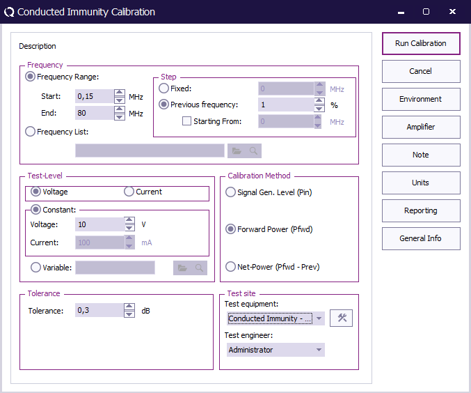
 Start Start
|
The start frequency of the calibration. For example 150 kHz.
|
| End
|
The stop frequency of the calibration. For example 80 MHz.
|
| Step
|
The frequency step, in this case 1%.
|
| Test level
|
The test level, in this case Voltage.
|
| Voltage
|
The voltage test level, 1 V, 3 V or 10 V.
|
| Tolerance
|
The regulation tolerance.
|
| Calibration method
|
The power measurement that should be the result of the calibration: Forward power
|
| Test equipment
|
Calibration test equipment.
|
| Test engineer
|
The engineer that performed the calibration.
|
When the calibration has finished, RadiMation® will ask to store the calibration file.
EUT Test[edit]
EUT testing equipment[edit]
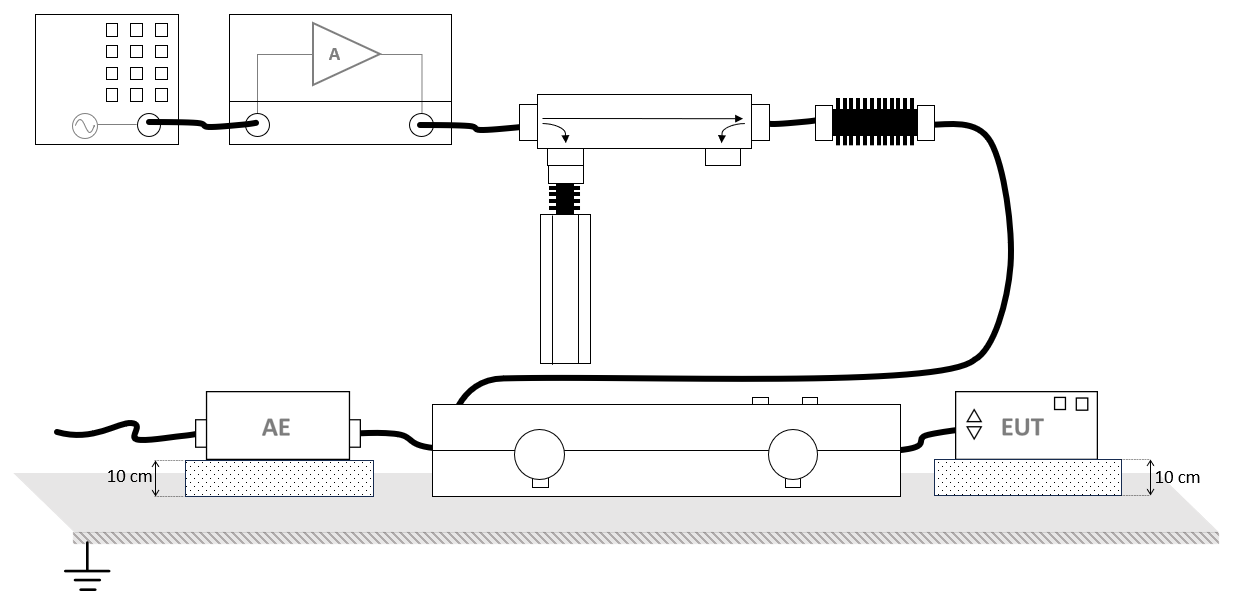
The configuration of the RadiMation® EUT test site should contain the following devices:
| # |
Device name |
Tab in testsite configuration window |
note
|
|
Signal Generator |
Devices 1 |
The signal generator to use
|
|
Amplifier |
Devices 1 |
The amplifier to use
|
|
Coupler |
Devices 1 |
The coupler to use
|
|
Forward power meter |
Devices 1 |
The forward power meter to use
|
|
Injection device |
Devices 2 |
The injection clamp or CDN to use
|
Configure the EUT test[edit]
To perform the actual test on the EUT, create a conducted immunity multiband test.
The conducted immunity multiband test configuration, can be opened by selecting from the menu:
- Tests
- Conducted Immunity
- Multiband
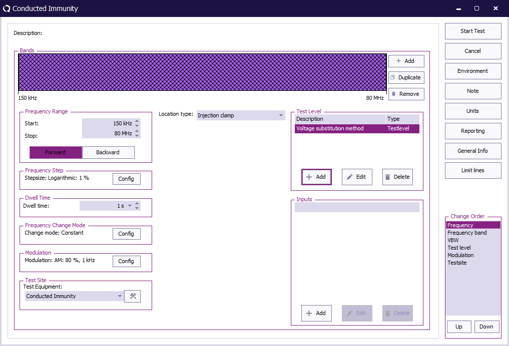
| Start
|
The start frequency of the test. For example 150 kHz.
|
| End
|
The stop frequency of the test. For example 80 MHz.
|
| Frequency Step
|
The frequency step, 1%.
|
| Dwell Time
|
The dwell time.
|
| Frequency Change Mode
|
The method that is used to change from one to the next frequency: Constant.
|
| Modulation
|
Configure Amplitude Modulation with 1 kHz and 80 % duty cycle.
|
| Test equipment
|
The equipment needed for the conducted immunity test.
|
| Location Type
|
Injection clamp.
|
| Test Level
|
Specify the Voltage substition method
|
| Inputs
|
No inputs are needed, this is optional.
|
To configure the modulation settings click Config next to the modulation settings, click the AM tab, and enter the amplitude modulation settings.
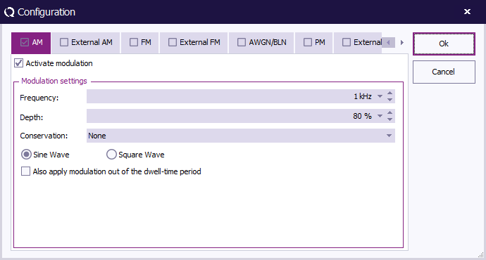
| Activate modulation
|
Check this checkbox to enable the amplitude modulation.
|
| Frequency
|
The AM frequency 1 kHz.
|
| Duty Cycle
|
A depth of 80 %.
|
| Also apply modulation out of the dwell-time period
|
No need to apply modulation out of the dwell-time period.
|
At TestLevel click Add to add a new Test level and select TestLevel - Voltage substitution method
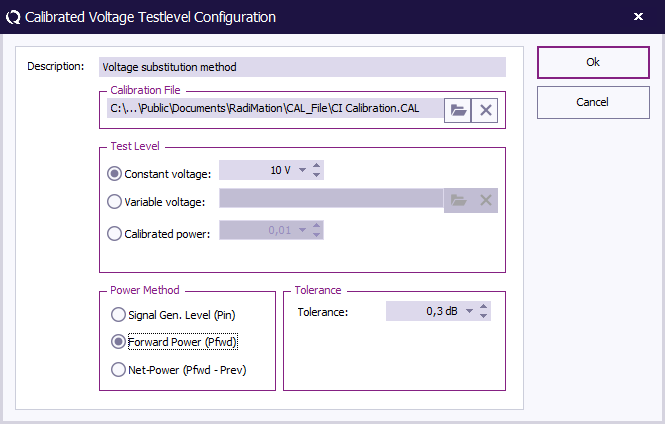
| Description
|
The description of the test level.
|
| Calibration file
|
Select the calibration file created during the calibration procedure.
|
| Test level
|
Constant voltage, 1 V, 3 V or 10 V.
|
| Calibration method
|
Select Forward Power.
|
| Tolerance
|
Specify the tolerance to use.
|
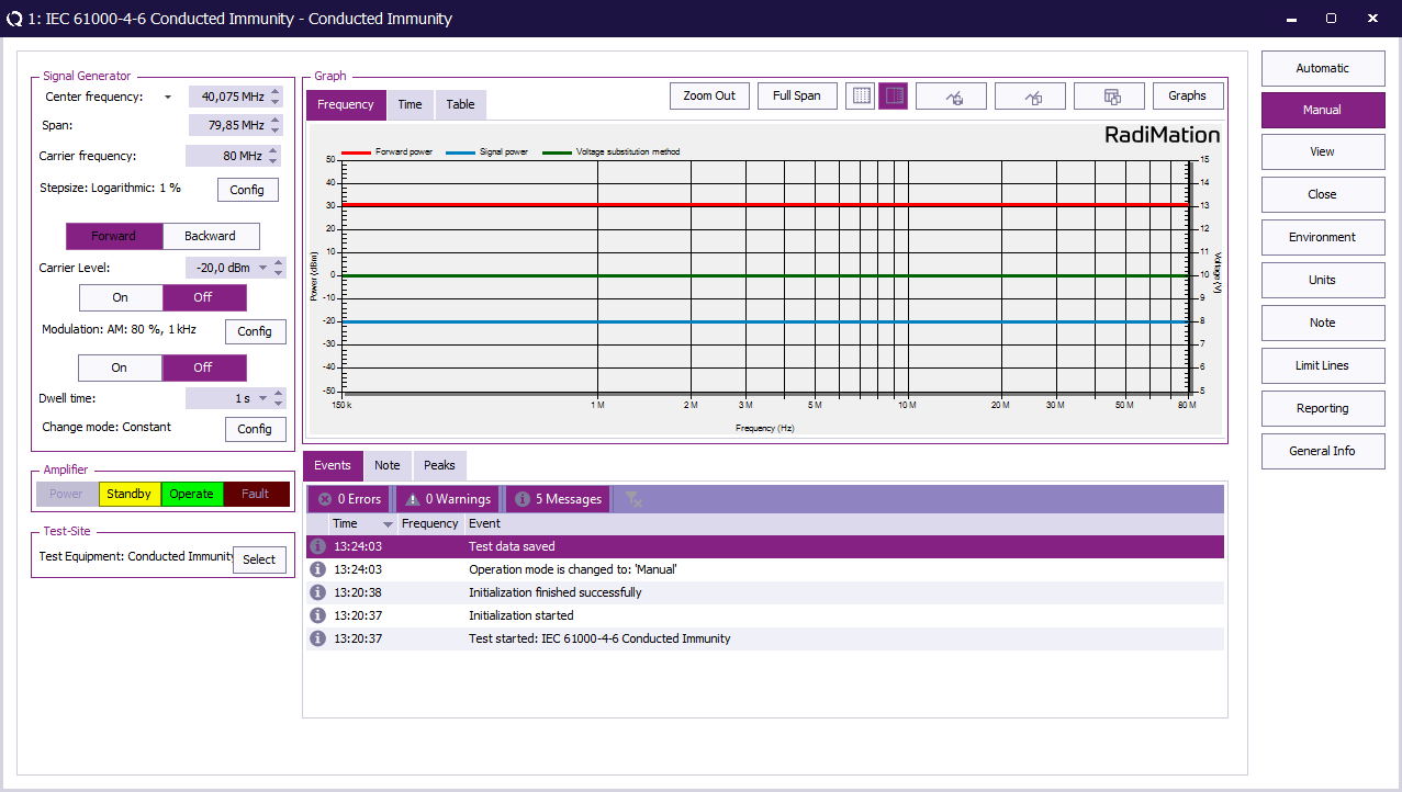
When all settings are configured press Start Test to run the EUT test.
EUT test result[edit]
Once the test is finished, the results of this test are stored in the EUT file and available as one of the performed Tests in the EUT file. Selecting the corresponding test result and pressing on Info will show the test results again.
Conclusion[edit]
The IEC 61000-4-6 calibration can be performed by using the Conducted immunity calibration. The RadiMation® Conducted immunity multiband test can then be used to perform the IEC 61000-4-6 EUT test with a calibration file in the EUT test.


