Radiated Emission Burst TSF
Jump to navigation
Jump to search
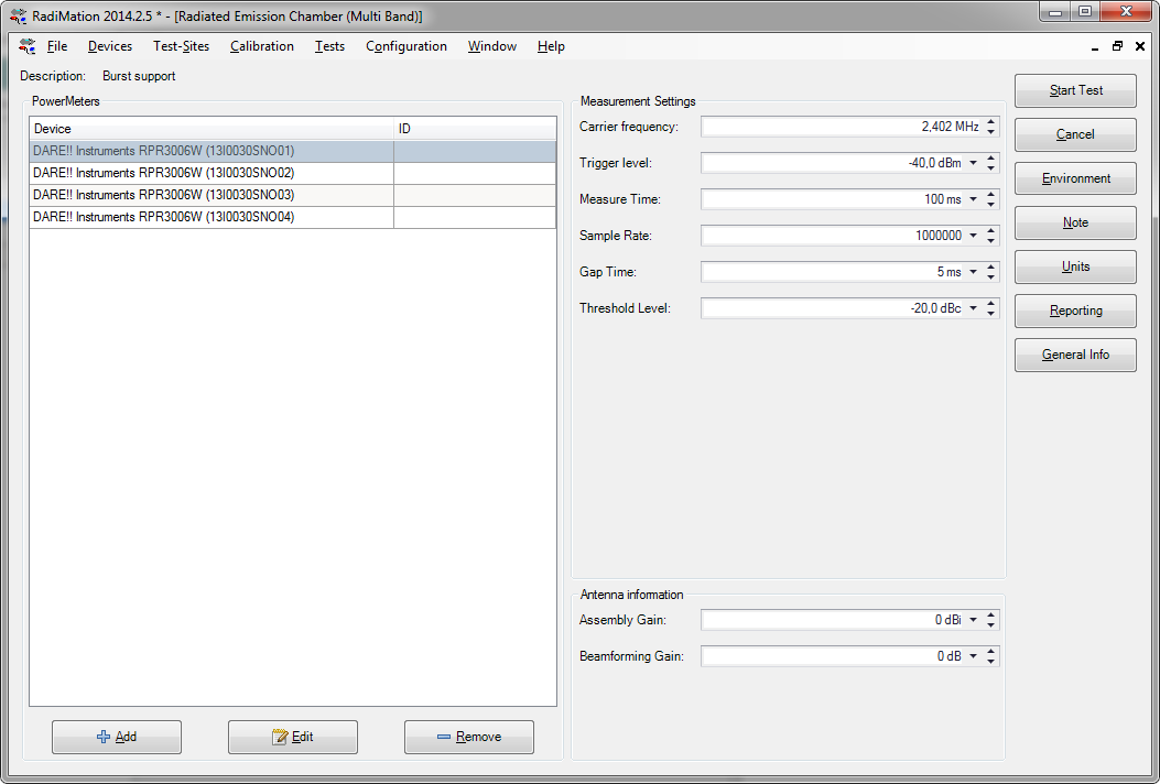
The following settings are available and can be configured:
| Shows the list of currently selected powermeters that will be used during the measurement |
| Allows to add one or more power meters to your test. |
| Shows the device driver configuration of the selected powermeter |
| Removes the selected powermeter from the list of powermeters that will be used |
| The primary frequency that will be measured by the powermeters. This frequency is used to correct the measurement result of the powermeters. |
| Specifies the power level for the trigger level of the powermeters. The powermeters will assume that a measurement sample is part of a burst if the measurement sample is above the specified Trigger level |
| The total time for the measurement |
| The sample rate that should be used by the powermeters |
| The Gap Time specifies the minimum time that the measurement samples should be below the Trigger level to designate that period of time as a gap in the transmission |
| The Threshold Level defines a dB difference to the maximum measured burst value, which is used to determine if a measured burst value is designated as a transmission. Any burst that has a maximum value that is more than Threshold Level below the maximum burst value during the complete Measure time will not be designated as a transmission. |
| The gain of the antenna that is normally connected to an output of the EUT. This Assembly Gain is used to calculate the total e.i.r.p. power. |
| The gain of the additional benefit of the combining of the multiple antenna's of the EUT. This Beamforming Factor is used to calculate the total e.i.r.p. power. |
