RadiMation Application Note 104
How to determine the current sensor transfer impedance[edit]
The transfer impedance of a current sensor is important and required to perform accurate current measurements. A typical current sensor transfer impedance can be retrieved form the manufacturer of the current sensor, or it can be determined in a calibration laboratory. It is however also possible to determine the transfer impedance of a current sensor yourself, if you have the correct equipment.
This Application Note explains how measurements can be done in RadiMation® to determine the transfer impedance of a current sensor. These measurements are done by using the Attenuation/Gain calibrations as they are provided by RadiMation®. After the Attenuation/Gain calibration is performed, some calculations are needed to determine the correct transfer impedance, however these can easily be done in Microsoft Excel. A verification of the calibration and recalculation of the data can be done to ensure that the expected current is indeed correctly measured by RadiMation®.
The equipment that is required for this measurement is:
- Signal generator
- Attenuator
- Calibration jig which is suitable for the to be calibrated current sensor
- Power meter, or a spectrum analyser that is used as a power meter.
- 50 Ω load
- Current sensor
Performing the Attenuation/Gain system calibration[edit]
First we need to determine the absolute difference between the signal generator and the power meter, before we can measure the transfer loss of the current sensor. Therefor we first have to perform the Attenuation/Gain system calibration as described in Chapter 12 of the manual.
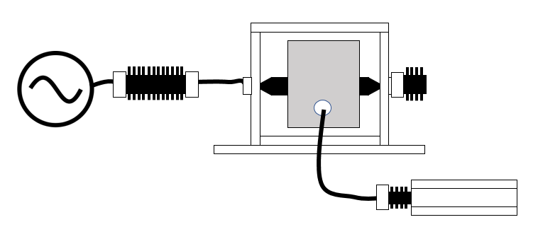
To ensure a higher accuracy it is advised to also include an attenuator and the calibration jig in the system calibration to arrange that the system calibration is very similar to the following EUT calibration. The attenuator is advised to be used to reduce mismatches between the signal generator and the calibration jig.
The measurement setup that should be used for this is:
Performing the Attenuation/Gain EUT calibration[edit]
After the absolute difference between the signal generator and powermeter is defined, the real transfer loss of the current sensor can be determined. Therefor we have to perform the Attenuation/Gain EUT calibration as described in Chapter 12 of the manual.
The measurement setup that should be used for this is:
Converting the measured data to a transfer impedance[edit]
Once the
Specifying the transfer impedance for the current sensor device driver[edit]
Verification[edit]
After the transfer impedance of the current sensor is determined and attached, it is also possible to verify if RadiMation® is able to measure the expected current.

