RadiMation Application Note 106
Powermeter parameter configuration[edit]
This application note describes how the measurement parameters of a Powermeter can be configured to get a fast and stable power measurement.
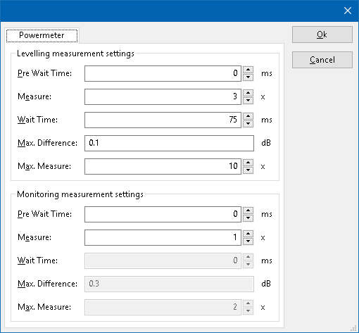
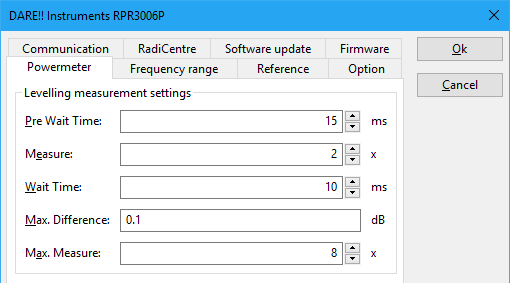
Each powermeter in RadiMation® has a powermeter configuration tab in the device drivers. In this tab, the accuracy of power measurement can be optimized. This function allows to make multiple measurements, and wait until the value is stable. Using a measurement-loop.
| Wait time before starting the measurement-loop. Can be used to wait for a signal generator, and or amplifier to stabalize. |
| The minimum ammount of measurements in the measure loop. Continues to loop even if power level is stable. |
| The wait time before each measurement is taken, during the measurement-loop. |
| If the measured power between each measurement in the measurement-loop, is less than this value. The measured power is stable. The loop will stop. |
| The maximum ammount of measure times, for the measurement-loop |
As can be seen on the screenshot. Both leveling, and monitoring settings can be set.
The leveling is used, whenever RadiMation is measuring the power, to regulate the signal generator.
For example, if you have a immunity power closed loop method. This will regulate the signal generator until certain power is measured.
In this case, the leveling settings are used.
If the powermeter is used as input. For example in the immunity multiband test, in the inputs table. Then the monitoring settings are used.
The leveling settings (for regulating the signal generator) should in general be set to measure quickly. This is because: If the measurement is slow, then this delay is multiplied by the amount of measure times the signal power regulation is needing. The monitoring settings on the other hand, can be in general set to a "slower"/"more accurate" measurement. Since that delay is not multiplied.
Example[edit]
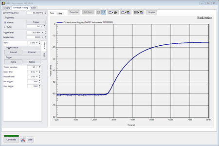
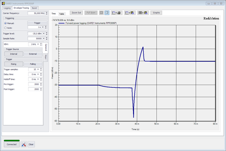
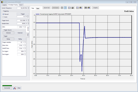
See the measured power graphs above. From left to right: Turning carrier on, change carrier up from -30 to -10, change carrier down from -10 to -20 dBm. As can be seen, the signal generator will require some time, to stabalize the output power. Left to right it takes about (45, 25 and 15ms) To assure correct powermeter measurement is being measured, we therefor should set the powermeter configurations accordingly. We will set the powermeter leveling settings, which are related to leveling the signal level. Changing the carrier, would atleast take 15ms. This would be our "Pre wait time". After the 15 ms, it could take about atleast up to 40 more ms, before output level would be stable. To be safe, we will use 80ms. We could split that 80 miliseconds, to 8 "Max measure times", with 10 ms "Wait time". When the output level is stable, the power is verry less fluctuating. We could set the "Max difference" to 0.1 dB. We specify that atleast 2 "Measure times", should be within this limit.
- If during a leveling, the carrier going up and down a lot. Then the measure-loop is going to fast, and should be slowed down.
- If measurement is slow, you can reduce the delays between measurement, or accept a bigger difference. Make sure (see first point) its not too fast.
| Warning: | With the available settings, you can make measurements very slow. In some cases, you can end up in measuring noise. Then the maximum measure times will be used. You may need to decrease the Max. Measure value in that case. |
