S-Parameters
Scattering parameters[edit]
S-parameters (or scattering parameters) are used to describe how energy can propagate through an electric network.
S-Parameters are used to describe the relationship between different ports, when it becomes especially important to describe a network in terms of amplitude and phase versus frequencies, rather than voltages and currents(1).
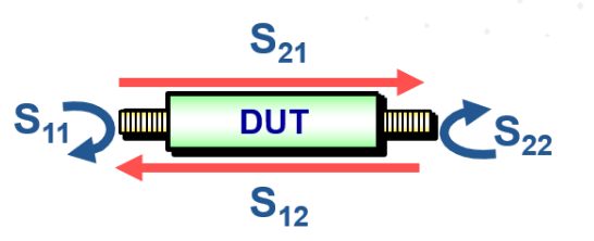
The image(3) seen below illustrates this for a 2 port system,
For example an set of S-Parameter tests on a 2 port DUT:
S11 – Reflection coefficient at port 1. A signal sent from port one of VNA and received at port one
S12 – Reverse transmission (gain/loss). Signal sent from port 2 of VNA and received at port 1
S21 – Forward transmission (gain/loss). Signal sent from port one of VNA and received at port 2
S22 – Reflection coefficient at port2. Signal sent from port 2 of VNA and received at port 2.
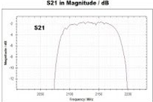
As an example the following image(2) shows an S21 insertion loss measurement performed on a bandpass filter.
Devices with more than two ports[edit]
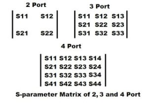
If the number of ports in a network increases, the s-parameter will become complex according to the number of ports.
Two port network has four parameters, three port will have nine parameter and so on.
The parameters of any given s-matrix are represented as Snn where S is the parameter and n is the number or port.
This is illustrated on the image(2) down below.
Sources[edit]
(1)https://www.everythingrf.com/community/what-are-s-parameters - Andreas Henkel, Aug 6, 2019
(2)https://www.rfpage.com/s-parameters-in-rf-testing-simple-explanation - March 19, 2016, Rajiv
(3)http://literature.cdn.keysight.com/litweb/pdf/5991-3736EN.pdf - Keysight Technologies, 2018, Published in USA, June 18, 2019, 5991-3736EN


