Category:Screenshot
Jump to navigation
Jump to search
This category contains all screenshots of software (not necessarily RadiMation), that are used on this RadiWiki site. This category is only used to have a 'manageable group' of all uploaded files that are screenshots.
Media in category "Screenshot"
The following 200 files are in this category, out of 342 total.
(previous page) (next page)- AddMonitoringInputDevice.png 807 × 597; 19 KB
- Address Information For Client.png 625 × 353; 14 KB
- Address Information For Manufacturer.png 625 × 353; 14 KB
- Address Information For test site.png 625 × 353; 13 KB
- Advanced options.png 1,281 × 795; 74 KB
- AmplifierResearchGainTab.png 510 × 144; 3 KB
- ApplicationNote123HighFrequencyTestsite.png 841 × 544; 46 KB
- ApplicationNote123LowFrequencyTestsite.png 841 × 544; 34 KB
- ApplicationNote123RelayACommunication.png 592 × 606; 18 KB
- ApplicationNote123RelayAName.png 709 × 457; 23 KB
- ApplicationNote123RelayARadiCentre.png 592 × 606; 17 KB
- ApplicationNote123RelayASwitches.png 592 × 606; 16 KB
- ApplicationNote123SwitchMatrixDeviceDrivers.png 1,053 × 541; 27 KB
- AppNote114ConfigurableADConvertor.png 651 × 590; 21 KB
- Attenuation Test Setup System Calibration.png 409 × 218; 7 KB
- CalibrationExporter.png 1,014 × 631; 30 KB
- CalibrationImport.png 683 × 554; 18 KB
- CANoe AD Convertor.png 492 × 368; 12 KB
- CARADControllerAddressSettings.png 392 × 246; 5 KB
- CE101 Test Configuration.png 994 × 725; 54 KB
- CE101 Test layout.png 859 × 427; 25 KB
- CE101 Test Result.png 1,286 × 860; 78 KB
- CE102 Test Configuration.png 994 × 725; 51 KB
- CE102 Test layout.png 976 × 484; 14 KB
- CE102 Test Result.png 1,282 × 910; 102 KB
- CentralHeatingBoilerDriverDriverSettings.png 735 × 788; 22 KB
- ConfdvdrFolder.png 1,451 × 746; 106 KB
- Config configuration.png 1,024 × 250; 11 KB
- Config-Config.png 943 × 156; 11 KB
- ConfigAmpDefault.PNG 511 × 466; 13 KB
- ConfigAmpDefaultOperation.PNG 511 × 465; 13 KB
- ConfigAmpMain.PNG 512 × 466; 14 KB
- ConfigAmpOperation.PNG 512 × 467; 15 KB
- Configurable AD Converter Configuration Window.png 650 × 591; 16 KB
- ConfigurableFrequencyRangeTab.png 526 × 305; 9 KB
- ConfigurableLISNLineCommandsTab.png 526 × 305; 7 KB
- ConfigurableLISNMainTab.png 526 × 305; 9 KB
- ConfigurableSwitchMatrixCustom1 HighFreq.png 544 × 491; 24 KB
- ConfigurableSwitchMatrixCustom1 LowFreq.png 544 × 491; 25 KB
- ConfigurableSwitchMatrixRS232Settings.png 544 × 491; 18 KB
- ConfigureCommunication.png 650 × 591; 18 KB
- ConfigureMonitoringInputChannel.png 663 × 575; 22 KB
- ConfigureMonitoringInputChannelFahrenheit.png 663 × 575; 22 KB
- CS109 Test Configuration.png 1,017 × 693; 39 KB
- CS109 Test level configuration.png 610 × 280; 11 KB
- CS109 Test level.png 1,011 × 507; 30 KB
- CS109 Test Result.png 1,277 × 850; 66 KB
- CS109 Test Setup.png 1,019 × 477; 32 KB
- CS114 Calibration band 1.png 677 × 566; 37 KB
- CS114 Calibration.png 1,177 × 496; 33 KB
- CS114 Current limit.png 610 × 280; 10 KB
- CS114 Current Testlevel Configuration.png 755 × 420; 23 KB
- CS114 EUT Testing.png 1,148 × 462; 37 KB
- CS114 Modulation settings.png 690 × 370; 14 KB
- CS114 Test level.png 1,123 × 557; 41 KB
- CS114 Test Result.png 1,283 × 850; 82 KB
- CS114 Test Setup.png 1,017 × 693; 40 KB
- CS114 Verification Result.png 1,283 × 850; 79 KB
- CS114 Verification Setup.png 1,017 × 693; 41 KB
- CS114 Verification.png 1,214 × 510; 32 KB
- Daqmx advanced.png 656 × 361; 21 KB
- DeviceDriverPreselector.png 558 × 150; 4 KB
- DeviceDriverTDEMIOptions.png 558 × 274; 11 KB
- Emco2090Softwarelimits.png 335 × 174; 5 KB
- ErrorReportFilesTab.png 564 × 554; 35 KB
- File Change Engineer.png 1,025 × 251; 11 KB
- Find directory.png 1,635 × 1,008; 47 KB
- Finddirectorys.png 1,635 × 1,008; 47 KB
- FixedStepCountConfiguration.png 445 × 263; 6 KB
- Full Splash screen.png 879 × 576; 179 KB
- GeneralTestInformationRetriever GeneralInformationItemsResult.png 511 × 353; 11 KB
- GeneralTestInformationRetriever GeneralInformationTab.png 559 × 462; 16 KB
- GPIB DeviceStream Configuration.png 554 × 429; 14 KB
- HTTPDeviceStreamConfiguration.png 544 × 491; 9 KB
- AddAction 1.PNG 841 × 514; 23 KB
- AddAction BeforeActions.PNG 841 × 514; 13 KB
- AddAction MessageBox.PNG 841 × 514; 22 KB
- AddACtion PopUp.PNG 353 × 133; 4 KB
- Amplifier Device Driver Can Not Be Configured Window.png 371 × 171; 14 KB
- Amplifier Protection Configuration Window.png 374 × 226; 5 KB
- Antenna Diagram Circle Flight Flow Chart.png 511 × 179; 5 KB
- Antenna Diagram Circle Flight Test Result Window.png 1,165 × 834; 53 KB
- Antenna Diagram Circle Flight Test Window.png 1,165 × 834; 51 KB
- Antenna Diagram Circle Flight Window.png 746 × 569; 25 KB
- Antenna Diagram Frequency Information Window Result Review.png 1,263 × 871; 44 KB
- Antenna Diagram Frequency Information Window Result.png 645 × 473; 20 KB
- Antenna Diagram Frequency Information Window.png 645 × 498; 28 KB
- Antenna Diagram Integrity Test Window.png 320 × 235; 7 KB
- Antenna Diagram Location Window.png 946 × 646; 25 KB
- Antenna Diagram Pilot Interface Circle Flight Window.png 647 × 486; 7 KB
- Antenna Diagram Pilot Interface Propagation Flight Window.png 647 × 486; 5 KB
- Antenna Diagram Pilot Interface Stand By Window.png 648 × 486; 3 KB
- Antenna Diagram Propagation Flight Window Result.png 1,263 × 871; 41 KB
- Antenna Diagram Propagation Flight Window.png 736 × 554; 25 KB
- Antenna Diagram Propagation Flow Chart.png 511 × 179; 5 KB
- Antenna Diagram Test Initialization Window.png 626 × 574; 16 KB
- Antenna Diagram Tower Information Window.png 541 × 346; 12 KB
- Antenna Diagram Vertical Flight Flow Chart.png 511 × 179; 5 KB
- Antenna Diagram Vertical Flight Test Result Window.png 995 × 847; 37 KB
- Antenna Diagram Vertical Flight Test Window.png 995 × 846; 35 KB
- Antenna Diagram Vertical Flight Window.png 767 × 562; 25 KB
- Attenuation system calibration Setup.png 515 × 194; 5 KB
- Basic standard details.png 1,089 × 845; 45 KB
- Browse Calibration File Directory.png 1,049 × 585; 47 KB
- Button arrow down.png 33 × 33; 500 bytes
- Button arrow up.png 33 × 33; 520 bytes
- Cable details.png 548 × 333; 10 KB
- Cables control.png 1,112 × 201; 7 KB
- Change Password.png 859 × 422; 18 KB
- ChangePassword.png 859 × 422; 18 KB
- Conducted Emission Absorbing Clamp Configuration Window.png 912 × 521; 39 KB
- Conducted Emission LISN Configuration Window.png 901 × 551; 38 KB
- Conducted Emission Manual Mode Export Tab.png 1,275 × 830; 34 KB
- Conducted Emission Manual Mode Limit Lines Tab.png 1,275 × 830; 35 KB
- Conducted Emission Manual Mode Peak Tab.png 1,275 × 830; 28 KB
- Conducted Emission Manual Mode Test.png 1,275 × 830; 46 KB
- Conducted Emission Manual Mode Traces Tab.png 1,275 × 830; 46 KB
- Conducted Immunity Substitution Configuration Window.png 916 × 673; 45 KB
- Conducted Immunity Test Setup Calibration.png 640 × 262; 73 KB
- Configurable Power Meter Window.png 528 × 565; 22 KB
- Configurable Signal Generator Window.png 515 × 679; 26 KB
- Configuration BasicStandards.png 1,049 × 585; 21 KB
- Configuration Database.png 1,049 × 585; 17 KB
- Configuration DeviceDrivers NewDeviceDriver.png 949 × 536; 70 KB
- Configuration DeviceDrivers.png 1,049 × 585; 25 KB
- Configuration Directories.png 1,049 × 585; 37 KB
- Configuration Graphs.png 1,049 × 585; 39 KB
- Configuration Language.png 1,049 × 585; 14 KB
- Configuration ProductStandards.png 1,049 × 585; 23 KB
- Configuration ReportGenerator.png 489 × 422; 6 KB
- Configuration Units.png 1,049 × 585; 27 KB
- Create new data source.png 468 × 345; 9 KB
- Customer Database Configuration Advanced.png 554 × 649; 35 KB
- Customer Database Configuration.png 639 × 705; 27 KB
- Default Address Information.png 814 × 630; 29 KB
- Define Text format one column.png 482 × 340; 6 KB
- Define Text format three columns.png 482 × 340; 6 KB
- Device Driver Configuration Window.png 554 × 124; 13 KB
- Device Driver Settings Window.png 731 × 722; 21 KB
- DirectRDCFileEdit.png 768 × 906; 38 KB
- DriversExeStartPage.PNG 499 × 387; 41 KB
- EM32 Ce01.JPG 1,024 × 768; 107 KB
- EM32 data reduction.JPG 1,024 × 768; 130 KB
- EM32 general.JPG 1,024 × 768; 119 KB
- EM32 graph emi 2.JPG 1,024 × 768; 113 KB
- EM32 graph emi.JPG 1,024 × 768; 158 KB
- EM32 humor.JPG 1,024 × 768; 192 KB
- EM32 Hw setup.JPG 1,024 × 768; 92 KB
- EM32 Hw setup2.JPG 1,024 × 768; 95 KB
- EM32 Hw setup3.JPG 1,024 × 768; 109 KB
- EM32 report.JPG 1,024 × 768; 116 KB
- Empty EUT File.png 751 × 669; 23 KB
- Engineers.png 468 × 284; 11 KB
- EnvironmentalDataEmpty.JPG 557 × 191; 21 KB
- EnvironmentalDataFilled.jpg 557 × 191; 23 KB
- EUT AD Channels Tab.jpg 984 × 667; 111 KB
- EUT Address Information.jpg 956 × 667; 91 KB
- EUT Information Tab Window.png 984 × 667; 26 KB
- EUT Reports Tab.jpg 449 × 161; 18 KB
- EUT Standards Tab.png 984 × 667; 17 KB
- Example EUT File.png 956 × 712; 19 KB
- Excel Export.png 760 × 488; 23 KB
- Field Probe Setup Configuration Window.png 383 × 307; 7 KB
- Field Sensor Configuration Window.png 510 × 490; 16 KB
- Flowchart EUT Attenuation Calibration.png 196 × 357; 3 KB
- Flowchart EUT Calibration Routine.png 415 × 814; 21 KB
- Flowchart System Compression Calibration.png 292 × 361; 11 KB
- Frequency Mode Stress Ramp Constant Fast Constant.png 864 × 727; 42 KB
- GPIB Address Configuration Window.png 413 × 277; 17 KB
- GPIB Address Configuration With Advanced Configuration Window.png 413 × 277; 17 KB
- GPIB Not Connected Window.png 736 × 240; 9 KB
- Graph Radiated Immunity Substitution Test.png 1,149 × 847; 38 KB
- GraphCustomization Chart.png 1,023 × 613; 136 KB
- GraphCustomization Graphs.png 1,019 × 596; 22 KB
- GraphCustomization Markers.png 1,021 × 596; 25 KB
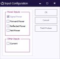
- Input Configuration Window.jpg 305 × 298; 22 KB
- Limitline file.png 968 × 560; 44 KB
- Manual Mode Continue Frequency.png 559 × 229; 6 KB
- Measurement Settings.PNG 1,049 × 585; 21 KB
- Menu Antenna Diagram Circle Flight.png 1,049 × 250; 13 KB
- Menu Antenna Diagram Integrity Test.png 1,049 × 250; 14 KB
- Menu Antenna Diagram Propagation Flight.png 1,049 × 250; 14 KB
- Menu Antenna Diagram Vertical Flight.png 1,049 × 250; 13 KB
- Menu File New Frequency.png 1,094 × 760; 42 KB
- Menu File New Location.png 1,049 × 250; 13 KB
- Menu Tests Radiated Immunity Fixed Field.png 1,049 × 300; 16 KB
- Menu Tests Radiated Immunity Fixed Power.png 1,049 × 300; 15 KB
- Menu Tests Radiated Immunity Substitution.png 1,049 × 300; 15 KB
- Menu Tests Radiated Immunity Triplate.png 1,049 × 300; 15 KB
- Msvistasp1-screen01.jpg 379 × 454; 36 KB
- Msvistasp1-screen02.jpg 785 × 579; 81 KB
- MultibandGraphInReport.jpg 855 × 577; 31 KB
- New AD Convertors Window.png 527 × 300; 8 KB
- New correction file.png 1,454 × 747; 35 KB
- NewEngineer.png 464 × 251; 14 KB
- NI Spy Options.png 439 × 540; 22 KB
- Note window.png 493 × 489; 10 KB
- Odbc data source administrator.png 471 × 390; 28 KB
- ODBC text setup.png 446 × 382; 5 KB
- Overlapping screen elements.jpg 1,024 × 768; 165 KB


