Rohde & Schwarz UPP800
The Rohde & Schwarz UPP800 device driver is a AD Converter which is supported by RadiMation®.
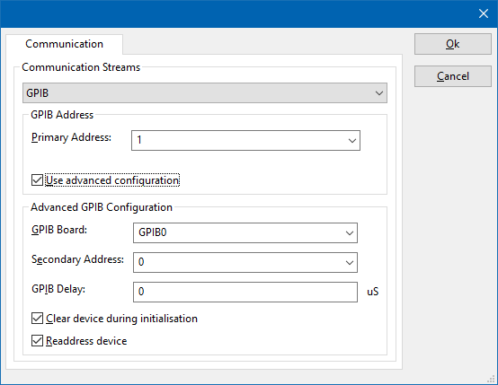
The advanced configuration window of the device driver contains the 'Communication' tab:
On the Communication tab, the desired communication method can be selected and configured. Depending on the selected method, additional relevant settings are shown and can be configured.
| Selects the medium or method that should be used to communicate with the device. Depending on the capabilities of the device this can be one or more of:
See the Communication Settings in Chapter 15, on how to configure each of these methods. |
The device driver for the Rohde & Schwarz UPP800 provides several EUT Monitoring channels that can be used during immunity testing to monitor the audio quality of the EUT.
The Rohde & Schwarz UPP800 allows that a lot of different audio measurements are performed, with a lot of different configuration combinations. Controlling all those settings from RadiMation® can be too limiting, and that is why RadiMation® will use the measurement configuration that is configured manually in the Rohde & Schwarz UPP800. It is thus important to realize that all the specific settings for the Rohde & Schwarz UPP800 are set by the test-engineer manually in the Rohde & Schwarz UPP800. RadiMation® will not reset or preset the Rohde & Schwarz UPP800, and will not change any measurement setting, and thus will use the settings as manually set by the test-engineer. Also no validation of the validity of these settings is performed. Only the results of the measurements of the Rohde & Schwarz UPP800 will be transferred to RadiMation.
The configuration of the EUT monitoring input in the EUT window, will allow to select the channel of the Rohde & Schwarz UPP800 that should be measured. There is however a difference in how the EUT Monitoring is configured between Singleband and Multiband tests.
Multiband immunity test[edit]
The Multiband immunity tests, are able to use a more user-friendly configuration of the EUT Monitoring inputs.
In a Multiband immunity test the EUT monitoring input is allowed to have a selection of a specific device driver, and the following channels:
- Channel 1 Function
- Channel 1 Level Monitor
- Channel 1 Input Monitor
- Channel 1 Freq/Phase
- Channel 2 Function
- Channel 2 Level Monitor
- Channel 2 Input Monitor
- Channel 2 Freq/Phase
- Channel 3 Function
- Channel 3 Level Monitor
- Channel 3 Input Monitor
- Channel 3 Freq/Phase
- Channel 4 Function
- Channel 4 Level Monitor
- Channel 4 Input Monitor
- Channel 4 Freq/Phase
The Rohde & Schwarz UPP200 will only allow to select the channels 1 and 2. The Rohde & Schwarz UPP400 will allow to select channels 1 to 4. The Rohde & Schwarz UPP800 will allow to select channels 1 to 8.
Singleband immunity test[edit]
In singleband immunity test the selection of the channel is restricted to be in the range of ‘Channel 1’ to ‘Channel 8’. The following mapping will be used to retrieve the desired value from the Rohde & Schwarz UPP800:
- EUT Monitoring Channel 1: Rohde & Schwarz UPP800 Channel 1 Function
- EUT Monitoring Channel 2: Rohde & Schwarz UPP800 Channel 1 Level Monitor
- EUT Monitoring Channel 3: Rohde & Schwarz UPP800 Channel 1 Input Monitor
- EUT Monitoring Channel 4: Rohde & Schwarz UPP800 Channel 1 Freq/Phase
- EUT Monitoring Channel 5: Rohde & Schwarz UPP800 Channel 2 Function
- EUT Monitoring Channel 6: Rohde & Schwarz UPP800 Channel 2 Level Monitor
- EUT Monitoring Channel 7: Rohde & Schwarz UPP800 Channel 2 Input Monitor
- EUT Monitoring Channel 8: Rohde & Schwarz UPP800 Channel 2 Freq/Phase
Channels[edit]
For each of the supported inputs of the Rohde & Schwarz UPP800, a ‘Function’, ‘Level Monitor’, ‘Input Monitor’ and ‘Freq/Phase’ selection is thus possible.
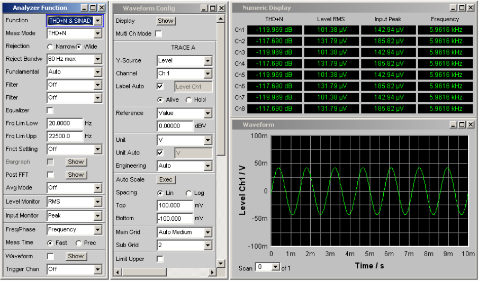
These channels are linked to the configuration as it is configured in the Rohde & Schwarz UPP800. A possible configuration in the Rohde & Schwarz UPP800 software is:
The settings and possible values on this configuration window are explained in the user manual of the Rohde & Schwarz UPP800.
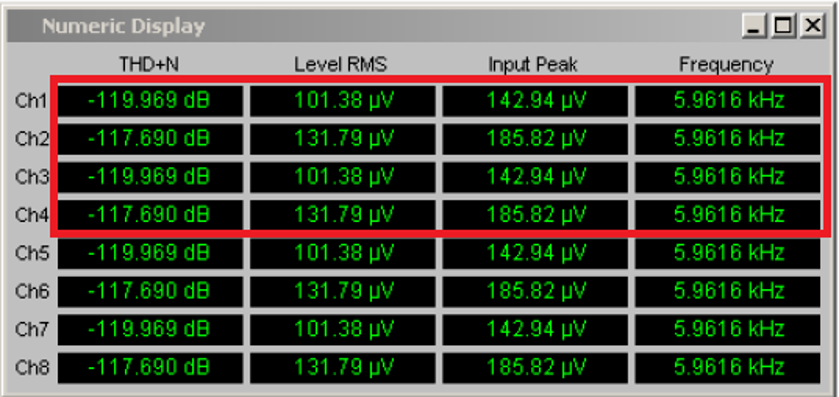
The numerical display of the Rohde & Schwarz UPP800 during a measurement is for example:
In the manual of the Rohde & Schwarz UPP800 it is described in section 3.3.9.1:
| “ | Das numerische Anzeigefeld fasst Zahlenwerte aus verschiedenen Analysatorfunktionen übersichtlich zusammen und stellt die maximal 8 Zahlenwert-Ergebnisse aus dem Panel "Analyzer Function" dar. Die einzelnen Spalten sind dabei von links nach rechts fest zugewiesen:
"Freq & Phase" bzw. "Freq & GrpDel", Anzeige des Frequenzmessergebnisses in der ersten Zeile und Anzeige der Phasen- bzw. Gruppenlaufzeitmessung in der zweiten Zeile. |
” |
The selection of the channel in the RadiMation device driver for the Rohde & Schwarz UPP800 correspond to those values.
- 'Channel <x> Function' corresponds to the selected 'Function' for that channel
- 'Channel <x> Level Monitor' corresponds to the selected 'Level Monitor' for that channel
- 'Channel <x> Input Monitor' corresponds to the selected 'Input Peak' for that channel
- 'Channel <x> Freq/Phase" corresponds to the selected 'Freq/Phase' for that channel
This will allow that up to 4x the number of supported channels (in multiband) or 8 (in singleband) EUT Monitoring channels are configured in the EUT file, where each channel is measuring the corresponding value of the numeric display.
A numerical value from the Rohde & Schwarz UPP800 will be reported in the standard basic SI unit. A 'Frequency' of 5.9616 kHz will thus be measured in RadiMation® as 5961.6 Hz. A 'RMS' value of 131.79 uV will thus be measured in RadiMation® as 0.00013179 V. The calculation options in the EUT monitoring channel in RadiMation can be used to convert and show these values to the desired value and unit.
If a measurement (like: Function, Level Monitor, Input Monitor or Freq/Phase) is not measured in the Rohde & Schwarz UPP800, RadiMation® will not raise an error that an unmeasured channel is selected. In the situation that an unmeasured channel is selected, the value will be represented as being 0.0.
If a measurement in the Rohde & Schwarz UPP800 was paused or stopped, the measurement will be automatically started, when the device driver is used in an immunity test in RadiMation®.
During the running immunity test in RadiMation® it is still possible to also view the measured values in the Rohde & Schwarz UPP800. Modifying the measurement configuration of the Rohde & Schwarz UPP800 during the running immunity test is not blocked. It is thus possible to change the configuration of the Rohde & Schwarz UPP800, and this could result in unaccredited measurement results.


