Why does a complete virtual clamp calibration fail
Why does a complete virtual clamp calibration fail?
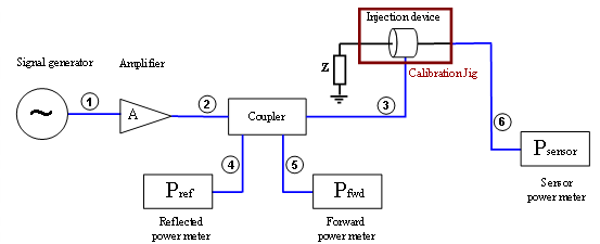
The current sensor power meter is used to measure the current in the set up.
The default configuration of the current sensor is to measure the current in a fixed current loop.
For this measurement you need to measure a lower power on the current sensor to simulate the correct current.
This means that with this set up it looks like you can not reach the desired current. Because the simulation is calculating a low current then you expect. It is not possible to make the simulation "aware" of the current type of measurement. The easiest way to overcome this problem is by adding a little attenuation to the sensor power meter.
We would suggest you add about 40 dB attenuation to the power meter, this is enough for generating about 30 mA.
| Note: | of course this is the same for the forward power meter, where the power is about 50 dB lower then the measured forward power |
