RadiMation Application Note 147
How to perform a MIL-STD RE101 Radiated Emission test[edit]
This application note explains how the MIL-STD RE101 Radiated Emission test can be performed with RadiMation®.
The "RE101, radiated emissions, magnetic field" test is applicable to equipment, subsystem enclosures and all interconnecting cables and is used to verify that the magnetic field emissions from the EUT and cabling do not exceed the specified requirements.
The exact requirements and test methods for the RE101 are specified in the MIL-STD-461.
Necessary equipment[edit]
The following devices are necessary to execute this test:
- Receiver
- Loop sensor (Antenna)
- LISN
- Cable
Configuration of the testsites[edit]
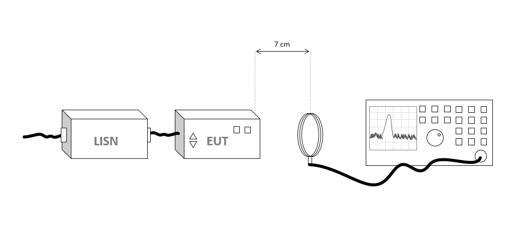
The configuration of the equipment is a loop sensor antenna connected with a cable to a receiver.
The configuration of the testsite should thus contain the following devices:
| Device name | Tab in testsite configuration window | note |
|---|---|---|
| Antenna | Devices 1 | Loop sensor antenna for the required frequency range |
| Spectrum Analyser | Devices 2 | The receiver used for the test |
| Cable preamp -> analyser | Cables | Cable with a correction file specified for the loss |
Note the lisn is only used to decouple and it is not needed to specify and configure this in RadiMation®
Configuration of the Loop sensor antenna[edit]
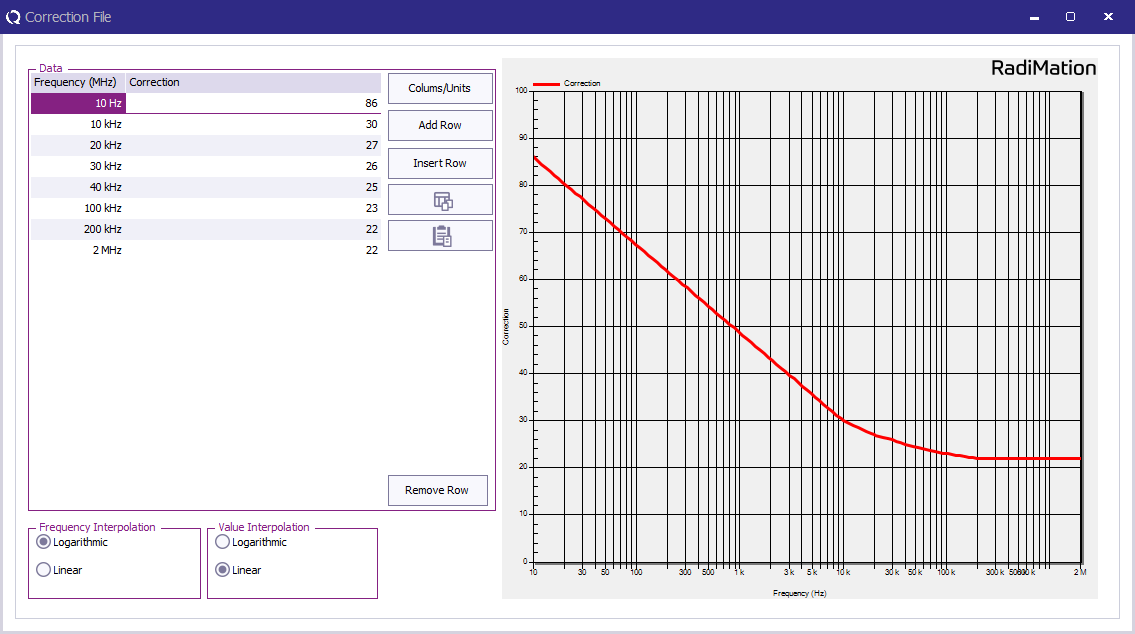
The loop antenna needs to have the correction data applied which is normally known by the manufacturer. The correction data is expressed in dBpT.
In RadiMation® this can be configured by creating a correction file, which contains a 'Frequency' and a 'Correction' column. Then specify the frequencies and the correction values in the correction file. The correction values are expressed in dBpT/uV.
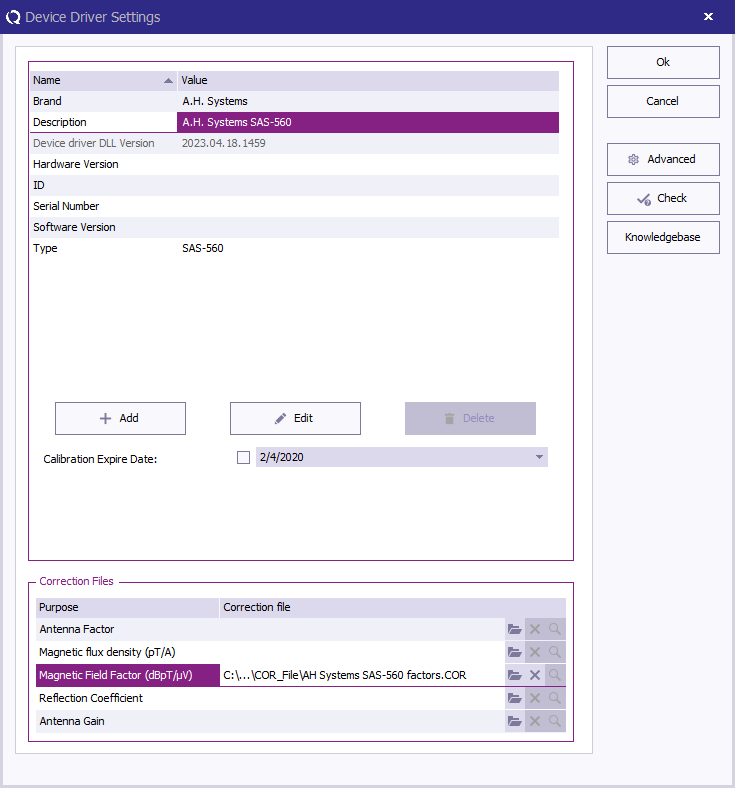
Once this correction is stored to disk, this correction file can be specified in the loop antenna driver configuration as 'Magnetic Field Factor':
Perform the test[edit]
To perform the actual RE101 test, start a Radiated Emission Multiband test:
-
 Tests
Tests
-
 Radiated Emission
-
 Multiband
-
-
-
The complete test from 30 Hz up to 150 kHz has different settings for different frequency bands. All these different bands can be configured. The test can be configured with 3 bands, each using their applicable frequency range, measure time and bandwidth.
| Band | Frequency range | RBW | Step size | Measure time receiver | Measure time FFT receiver |
|---|---|---|---|---|---|
| Band 1 | 30 Hz - 1 kHz | 10 Hz | 5 Hz | 0.15 s | 1 s |
| Band 2 | 1 kHz - 10 kHz | 100 Hz | 50 Hz | 0.015 s | 1 s |
| Band 3 | 10 kHz - 150 kHz | 1 kHz | 500 Hz | 0.015 s | 1 s |


