Difference between revisions of "CANoe"
(→Retrieving information from CANoe into RadiMation) |
|||
| Line 5: | Line 5: | ||
= Retrieving information from CANoe into RadiMation = | = Retrieving information from CANoe into RadiMation = | ||
| − | Use the | + | Use the {{ScreenElement|[[CANoe Interface]]}} AD Convertor device driver to read out measurement values from the CANoe Software into RadiMation. |
To connect with RadiMation you need to configure the following things: | To connect with RadiMation you need to configure the following things: | ||
# Create the [[CANoe Interface]] device driver (as an AD Convertor) in RadiMation. | # Create the [[CANoe Interface]] device driver (as an AD Convertor) in RadiMation. | ||
| + | # Start the CANoe software, and load the desired configuration. | ||
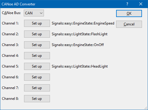
| + | # Open the 'Advanced' settings window of the '''CANoe Interface''' device driver. <BR>[[File:CANoe AD Convertor.png]]<BR>Use the {{ScreenElement|Set up}} buttons to select up to 8 measurement values from the CAN bus, that should be transferred to RadiMation. | ||
# Select the created [[CANoe Interface]] device driver as an AD convertor in the testsite that is used during an immunity test. | # Select the created [[CANoe Interface]] device driver as an AD convertor in the testsite that is used during an immunity test. | ||
| − | # Configure the EUT Monitoring inputs in RadiMation to measure values from the selected AD Convertor | + | # Configure the EUT Monitoring inputs in RadiMation to measure values from the selected AD Convertor. Normally for each channel that is selected in the '''CANoe Interface''' device driver, a matching EUT Monitoring input should be created. |
When an immunity test is started, all the activated EUT Monitoring inputs will be measured on each test frequency, and thus the data from the CAN bus (through the CANoe software) will also be included in RadiMation. | When an immunity test is started, all the activated EUT Monitoring inputs will be measured on each test frequency, and thus the data from the CAN bus (through the CANoe software) will also be included in RadiMation. | ||
Revision as of 10:09, 15 September 2017
CANoe and CANalyzer are software packages from Vector Informatik which can be used to control and monitor the CAN bus or LIN bus.
It is possible to retrieve measurement values from the CAN bus into RadiMation. And it is also possible to transfer measurement values from RadiMation to the CANoe software, which allows to put the RadiMation measurement values on the CAN bus. Each of these data transfer directions can be used in a RadiMation immunity test, and it is even possible to use both data transfer directions in the same immunity test.
Contents
Retrieving information from CANoe into RadiMation
Use the CANoe Interface AD Convertor device driver to read out measurement values from the CANoe Software into RadiMation.
To connect with RadiMation you need to configure the following things:
- Create the CANoe Interface device driver (as an AD Convertor) in RadiMation.
- Start the CANoe software, and load the desired configuration.
- Open the 'Advanced' settings window of the CANoe Interface device driver.
Use the Set up buttons to select up to 8 measurement values from the CAN bus, that should be transferred to RadiMation. - Select the created CANoe Interface device driver as an AD convertor in the testsite that is used during an immunity test.
- Configure the EUT Monitoring inputs in RadiMation to measure values from the selected AD Convertor. Normally for each channel that is selected in the CANoe Interface device driver, a matching EUT Monitoring input should be created.

When an immunity test is started, all the activated EUT Monitoring inputs will be measured on each test frequency, and thus the data from the CAN bus (through the CANoe software) will also be included in RadiMation.
Supplying RadiMation values to CANoe
It is possible to supply RadiMation values to CAN bus through the CANoe/CANalyzer software. The exact details on how this should be done is however very depending on the implementation of the units on the CAN bus. To allow a lot of flexibility, RadiMation is using CAPL functions, which allow to specify the exact details on how the information should be used on the CAN bus. Using the CAPL interface allows for full flexibility on the implementation and details.
CAPL
CANoe supports CAPL, a programming interface designed by Vector Informatik. Through this interface RadiMation can send information back the CANoe software. For Example:
- Frequency
- Field Strength
- Signal power
- Forward power
- Current
- Turntable angle
- Antenna height
- Antenna polarization
- ... (and more)
RadiMation connects through COM to this application, which requires that the CANoe software should be installed on the same PC.
To connect with RadiMation you need to configure the following things:
- Create the CANoe Switch Matrix device driver in RadiMation.
- Select the created CANoe Switch Matrix device driver in the testsite that is used during an immunity test.
- Include the RadiMationInterface.can file inside your CANoe/CANalyser project. The contents of the RadiMationInterface.can file can be extended to take specific action.
Note that the functions in the RadiMationInterface.can file do not support a callback to the RadiMation application. So this CAPL interface can only be used to have updates of measurement values and settings during a test from RadiMation to CANoe or CANalyser.
|
Events in the CAPL interface
The events given to the CAPL interface are event triggered. This means that the information is send the moment it becomes available.
For example, when the Forward power has been measured the forward power information is send through the interface. The same goes for a frequency change.
This also means that when information is not available, for example the test is done only on signal generator level then the forward power will not be send at all.
Which events are triggered, and how often they are triggered is completely dependent on the configuration of the TSF in RadiMation®.
When filtering of the events is required then this can be implemented in the CANoe software.