Difference between revisions of "Chapter 15"
| Line 16: | Line 16: | ||
==Device specific configuration== | ==Device specific configuration== | ||
===Signal generator=== | ===Signal generator=== | ||
| − | Pressing advanced will open an IEEE configuration screen. Please view chapter IEEE setting for a complete description. See | + | Pressing advanced will open an IEEE configuration screen. Please view chapter IEEE setting for a complete description. See {{ManualLink|14|Correction files}} and {{ManualLink|14|Correction file uses}} for correcting this device. |
===Amplifier=== | ===Amplifier=== | ||
| − | When an amplifier can be remotely controlled the specific window will appear. Please view chapter IEEE or RS232 setting for a complete description. When the amplifier can not be remotely controlled the message This Device cannot be configured will appear. See | + | When an amplifier can be remotely controlled the specific window will appear. Please view chapter IEEE or RS232 setting for a complete description. When the amplifier can not be remotely controlled the message This Device cannot be configured will appear. See {{ManualLink|14|Correction files}} and {{ManualLink|14|Correction file uses}} for correcting and protecting this device. |
===Antenna=== | ===Antenna=== | ||
| − | When pressing advanced the message This Device cannot be configured will appear because this device can not be controlled remotely. See | + | When pressing advanced the message This Device cannot be configured will appear because this device can not be controlled remotely. See {{ManualLink|14|Correction files}} and {{ManualLink|14|Correction file uses}} for correcting this device. |
===Coupler=== | ===Coupler=== | ||
| − | When pressing advanced the message This Device cannot be configured will appear because this device can not be controlled remotely. See | + | When pressing advanced the message This Device cannot be configured will appear because this device can not be controlled remotely. See {{ManualLink|14|Correction files}} and {{ManualLink|14|Correction file uses}} for correcting this device. |
===Powermeter=== | ===Powermeter=== | ||
| Line 40: | Line 40: | ||
new one. Determines the minimum, maximum and difference again. This continues as long as the difference is larger then defined and the maximum amount of measurement has not yet been reached. If the maximum amount of measurement has been reached the last measurement is taken as the measured value. | new one. Determines the minimum, maximum and difference again. This continues as long as the difference is larger then defined and the maximum amount of measurement has not yet been reached. If the maximum amount of measurement has been reached the last measurement is taken as the measured value. | ||
| − | See | + | See {{ManualLink|14|Correction files}} and {{ManualLink|14|Correction file uses}} for correcting this device. |
{{Note|'''Speed up(1):''' Sometimes slower means faster. For instance, if you have a slower powermeter (resistor head) it may be quicker to have a longer waiting time. Because the powermeter has more time to determine the right value, {{RadiMation}} needs less measurements to determine the value. It is up to the engineer to find the right accuracy vs. time setting. | {{Note|'''Speed up(1):''' Sometimes slower means faster. For instance, if you have a slower powermeter (resistor head) it may be quicker to have a longer waiting time. Because the powermeter has more time to determine the right value, {{RadiMation}} needs less measurements to determine the value. It is up to the engineer to find the right accuracy vs. time setting. | ||
| Line 69: | Line 69: | ||
===Injection device=== | ===Injection device=== | ||
| − | When pressing advanced the message This Device cannot be configured will appear because this device can not be controlled remotely. See | + | When pressing advanced the message This Device cannot be configured will appear because this device can not be controlled remotely. See {{ManualLink|14|Correction files}} and {{ManualLink|14|Correction file uses}} for correcting this device. |
===Calibration Jigs=== | ===Calibration Jigs=== | ||
| − | When pressing advanced the message This Device cannot be configured will appear because this device can not be controlled remotely. See | + | When pressing advanced the message This Device cannot be configured will appear because this device can not be controlled remotely. See {{ManualLink|14|Correction files}} and {{ManualLink|14|Correction file uses}} for correcting this device. |
===Current Sensor=== | ===Current Sensor=== | ||
| − | When pressing advanced the message This Device cannot be configured will appear because this device can not be controlled remotely. See | + | When pressing advanced the message This Device cannot be configured will appear because this device can not be controlled remotely. See {{ManualLink|14|Correction files}} and {{ManualLink|14|Correction file uses}} for correcting this device. |
===Pre Amplifiers=== | ===Pre Amplifiers=== | ||
| − | When pressing advanced the message This Device cannot be configured will appear because this device can not be controlled remotely. See | + | When pressing advanced the message This Device cannot be configured will appear because this device can not be controlled remotely. See {{ManualLink|14|Correction files}} and {{ManualLink|14|Correction file uses}} for correcting this device. |
===Receivers / Spectrum analyser=== | ===Receivers / Spectrum analyser=== | ||
| − | Pressing advanced will open an IEEE configuration screen. Please view chapter IEEE setting for a complete description. | + | Pressing advanced will open an IEEE configuration screen. Please view chapter IEEE setting for a complete description. See {{ManualLink|14|Correction files}} and {{ManualLink|14|Correction file uses}} for correcting this device. |
===LISN=== | ===LISN=== | ||
| − | When an LISN can be remotely controlled the specific window will appear. Please view chapter IEEE or RS232 setting for a complete description. When the LISN can not be remotely controlled the message This Device cannot be configured will appear. See | + | When an LISN can be remotely controlled the specific window will appear. Please view chapter IEEE or RS232 setting for a complete description. When the LISN can not be remotely controlled the message This Device cannot be configured will appear. See {{ManualLink|14|Correction files}} and {{ManualLink|14|Correction file uses}} for correcting this device. |
===Turn Table=== | ===Turn Table=== | ||
| Line 93: | Line 93: | ||
===Absorbing Clamps=== | ===Absorbing Clamps=== | ||
| − | When pressing advanced the message This Device cannot be configured will appear because this device can not be controlled remotely. See | + | When pressing advanced the message This Device cannot be configured will appear because this device can not be controlled remotely. See {{ManualLink|14|Correction files}} and {{ManualLink|14|Correction file uses}} for correcting this device. |
===Clamp positioner=== | ===Clamp positioner=== | ||
| Line 99: | Line 99: | ||
===Cables=== | ===Cables=== | ||
| − | When pressing advanced the message This Device cannot be configured will appear because this device can not be controlled remotely. See | + | When pressing advanced the message This Device cannot be configured will appear because this device can not be controlled remotely. See {{ManualLink|14|Correction files}} and {{ManualLink|14|Correction file uses}} for correcting this device. |
===Switch matrix=== | ===Switch matrix=== | ||
| Line 346: | Line 346: | ||
This message box is displayed when {{RadiMation}} is trying to locate a device driver and was unable to find it. If you see this message please contact your reseller and tell him which driver you are trying to use. The reseller will take action so that you will receive the right device driver. | This message box is displayed when {{RadiMation}} is trying to locate a device driver and was unable to find it. If you see this message please contact your reseller and tell him which driver you are trying to use. The reseller will take action so that you will receive the right device driver. | ||
| − | === GPIB: Device is not connected=== | + | ===GPIB: Device is not connected=== |
[[Image:GPIB Not Connected Window.png]] | [[Image:GPIB Not Connected Window.png]] | ||
Revision as of 12:41, 20 February 2011
Device drivers
Introduction
Device drivers are the lowest layer in RadiMation®, they make it possible to communicate with thousands of different devices. They make the system flexible, while the RadiMation® Core stays generic. The RadiMation® Core does not even know which device it is controlling, only the type of device. So if you have bought a new spectrum analyser or signal generator you only have to tell the software to use this new device and all the rest stays the same.
This chapter only describes the device driver specific configuration. All the configuration of the device drivers that are managed by the RadiMation® Core, are described in Chapter 14: Device driver configuration. Also the common device driver settings are described in Chapter 14: Device Driver settings.
Virtual device drivers
For testing and demonstration purposes, virtual device drivers are added as well. These virtual device drivers act as a normal device but do not control real hardware.
Virtual device drivers do not have limitations like normal device drivers (like frequency band, maximum power, sweep times, etc.)
Configurable device drivers and non-configurable device drivers
RadiMation® supports two types of device drivers, configurable and non-configurable device drivers. Configurable devices for instance are powermeter, signal generators and spectrum analysers. For these devices you can set the IEEE address or the serial port which RadiMation® has to use to be able to communicate with these devices. Non-configurable devices are couplers and calibration jigs. You might think that it is useless to have non-configurable drivers, but the opposite has been proven many times. Non-configurable drivers still contain important information like the start and stop frequency of a device. With this information RadiMation® can prevent the test engineer from making large mistakes, like using the wrong coupler in a certain frequency range.
Device specific configuration
Signal generator
Pressing advanced will open an IEEE configuration screen. Please view chapter IEEE setting for a complete description. See Chapter 14: Correction files and Chapter 14: Correction file uses for correcting this device.
Amplifier
When an amplifier can be remotely controlled the specific window will appear. Please view chapter IEEE or RS232 setting for a complete description. When the amplifier can not be remotely controlled the message This Device cannot be configured will appear. See Chapter 14: Correction files and Chapter 14: Correction file uses for correcting and protecting this device.
Antenna
When pressing advanced the message This Device cannot be configured will appear because this device can not be controlled remotely. See Chapter 14: Correction files and Chapter 14: Correction file uses for correcting this device.
Coupler
When pressing advanced the message This Device cannot be configured will appear because this device can not be controlled remotely. See Chapter 14: Correction files and Chapter 14: Correction file uses for correcting this device.
Powermeter

| Wait time is the time that RadiMation® may take for one measurement |
| The maximum allowed difference between the minimum and the maximum of measurements defined in the measurement window. |
| Measure is the minimum amount of measurements RadiMation® has to make to determine the power. |
| Maximum measurement is the maximum amount of measurement RadiMation® may take to determine the power. |
Now that all windows have been generally explained, the procedure RadiMation® uses is the following. RadiMation® takes the amount of measurements as defined in the Measure window. After that RadiMation® determines the minimum, maximum and difference. When the difference is equal or smaller then defined in Max difference RadiMation® determines the power. If the difference is greater then defined, RadiMation® takes one new measurement. Replaces the oldest value with the
new one. Determines the minimum, maximum and difference again. This continues as long as the difference is larger then defined and the maximum amount of measurement has not yet been reached. If the maximum amount of measurement has been reached the last measurement is taken as the measured value.
See Chapter 14: Correction files and Chapter 14: Correction file uses for correcting this device.
|
Field Sensor

| Wait time is the time that RadiMation® may take for one measurement. |
| The maximum allowed difference between the minimum and the maximum of measurements defined in the measurement window. |
| Measure is the minimum amount of measurements RadiMation® has to make to determine the field. |
| Maximum measurement is the maximum amount of measurement RadiMation® may take to determine the field. |
| Opens the advanced menu, this can be RS 232, IEEE or device specific settings like Range mode. |
Now that all windows and buttons have been generally explained, the procedure RadiMation® uses is the following. RadiMation® takes the amount of measurements as defined in the Measure window. After that RadiMation® determines the minimum, maximum and difference. When the difference is equal or smaller then defined in Max difference RadiMation® determines the field. If the difference is greater then defined, RadiMation® takes one new measurement. Replaces the oldest value with the
new one. Determines the minimum, maximum and difference again. This continues as long as the difference is larger then defined and the maximum amount of measurement has not yet been reached. If the maximum amount of measurement has been reached the last measurement is taken as the measured value.
|
AD converter
When an ad converter can be remotely controlled the specific window will appear. Please view chapter IEEE or RS232 setting for a complete description. When the ad converter can not be remotely controlled the message This Device cannot be configured will appear.
Injection device
When pressing advanced the message This Device cannot be configured will appear because this device can not be controlled remotely. See Chapter 14: Correction files and Chapter 14: Correction file uses for correcting this device.
Calibration Jigs
When pressing advanced the message This Device cannot be configured will appear because this device can not be controlled remotely. See Chapter 14: Correction files and Chapter 14: Correction file uses for correcting this device.
Current Sensor
When pressing advanced the message This Device cannot be configured will appear because this device can not be controlled remotely. See Chapter 14: Correction files and Chapter 14: Correction file uses for correcting this device.
Pre Amplifiers
When pressing advanced the message This Device cannot be configured will appear because this device can not be controlled remotely. See Chapter 14: Correction files and Chapter 14: Correction file uses for correcting this device.
Receivers / Spectrum analyser
Pressing advanced will open an IEEE configuration screen. Please view chapter IEEE setting for a complete description. See Chapter 14: Correction files and Chapter 14: Correction file uses for correcting this device.
LISN
When an LISN can be remotely controlled the specific window will appear. Please view chapter IEEE or RS232 setting for a complete description. When the LISN can not be remotely controlled the message This Device cannot be configured will appear. See Chapter 14: Correction files and Chapter 14: Correction file uses for correcting this device.
Turn Table
Pressing advanced will open an IEEE configuration screen. Please view chapter IEEE setting for a complete description.
Antenna Tower
Pressing advanced will open an IEEE configuration screen. Please view chapter IEEE setting for a complete description.
Absorbing Clamps
When pressing advanced the message This Device cannot be configured will appear because this device can not be controlled remotely. See Chapter 14: Correction files and Chapter 14: Correction file uses for correcting this device.
Clamp positioner
When a clamp positioner can be remotely controlled the specific window will appear. Please view chapter IEEE or RS232 setting for a complete description. When the clamp positioner can not be remotely controlled the message This Device cannot be configured will appear.
Cables
When pressing advanced the message This Device cannot be configured will appear because this device can not be controlled remotely. See Chapter 14: Correction files and Chapter 14: Correction file uses for correcting this device.
Switch matrix
When a switch matrix can be remotely controlled the specific window will appear. Please view chapter IEEE or RS232 setting for a complete description. When the switch matrix can not be remotely controlled the message This Device cannot be configured will appear.
EUT Controller
When a EUT Controller can be remotely controlled the specific window will appear. Please view chapter IEEE or RS232 setting for a complete description. When the EUT Controller can not be remotely controlled the message This Device cannot be configured will appear.
Communication settings
Depending on the brand and model of the device, it may be necessary to specify the parameters for the communication with the device. The IEEE 488 and RS232 buses are most commonly used. This section describes the relevant communication parameters.
RS 232 Setting

In the textbox you can type the COM port which RadiMation® has to use to able to communicate with the device. Baudrate, 7 or 8 bits and parity do not need to set because this is device specific.
IEEE Setting Basic

| The primary address specifies the address of the device, so if the device you want to configure is on address is on 20 you enter 20. Please consult the manual of the device how to get the GPIB address of the device. |
| Advanced configuration enables the user to setup the GPIB board. The configuration is discussed in “IEEE settings advanced” This option should only be used if the default settings are not sufficient enough. |
IEEE Setting advanced
The GPIB Address Configuration dialog is used to specify the GPIB communication parameters, for the communication with a measurement device.

| The primary address specifies the address of the device, so if the device you want to configure is on address is on 20 you enter 20. Please consult the manual of the device how to determine the GPIB address of the device. |
| Allows the end-user to enables the more advanced configuration parameters. |
| With GPIB Board you can specify the GPIB board that is used. The default value is 0 and can only be different when multiple GPIB boards are present. |
| The second address is default 0, and should only be changed when needed. For further information please look in the help of National Instruments 488.2. |
| GPIB delay is the delay between GPIB reading and writing actions. Some older IEEE 488.2 machines have difficulty communicating with fast PC's (> 2.5 GHz). This is most of the time noticeable when a driver is sometimes working and some times gives a GPIB (EABO or TIMO) error. These errors are most of the time, generated randomly. Specifying a GPIB delay time of 3000 uSeconds can fix these random errors. Run the test again and see of the problem as disappeared. Is the problem has disappear then your problem was timing, if not please contact your reseller and report the problems you are having. |
| Enabling this checkbox will send a reset to the device during initialisation. |
| Enabling this checkbox will. |
| Saves and closes the dialog |
| Closes the dialog, without saving the changes |
Virtual devices
Virtual devices are devices that act like normal devices but do not really exist. If you create a test site with only virtual devices, you can perform complete virtual tests. You might wonder why RadiMation® supports virtual device drivers. It is mainly used for debugging and solving software problems, but is has proven to be very useful when used as a temporarily workaround. For example a test site has an amplifier that is IEEE controlled and one day somebody accidentally destroys the communication between computer and amplifier. The test engineer has to perform some tests, he switches the driver for the amplifier for a virtual one. Sets the amplifier in operate by hand and was able to perform the tests that day. When the communication was repaired he changed the driver back again
Configurable devices
RadiMation® allows the user to create its own device drivers for test equipment, which is (not yet) implemented in the standard device driver list.
User configurable device drivers are available for nearly all types of test equipment. However, device drivers for spectrum analysers and measurement receivers can not be made with user configurable device drivers because the complexity (and differences between suppliers) of these devices is too high.
To make your own device driver, use the “Device drivers” tab in the “Configuration” > “Configuration” menu and follow the steps below:
- In the device driver’s menu, select the required device driver type.
- Press the “New” button.
- Select the driver called “Configurable xx” (i.e. if you want to make a signal generator device driver you would select the “Configurable signal generator” device driver).
- Enter a description for the device driver (for example the type number of the generator) and press OK.
- The name of the device driver will be added in the available device driver’s list.
- Select the new device driver from the available device device’s list.
- Press the “Edit” button.
- A configuration screen for the device driver will appear. All required control commands for the device must be entered. Refer to the operating manual of the equipment for these codes.
After all codes are entered, the device driver is ready for use.
The custom-made device driver can be used as any other device driver by selecting the driver in the Equipment list.
|
The reason for this is that RadiMation® has to know a number of parameters of these devices. Among others the following information is relevant:
- Frequency range
- Maximum input power
- The report generator needs to know which equipment is used during a test
- Correction files for these devices
Generic settings
Start and stop frequency
The most generic setting is the start and stop frequency. The default value for the start frequency is 1Hz and for the stop frequency is 40 GHz. The creator of the device is encouraged to set the right start and stop frequency. If the start and stop frequency are set correctly RadiMation® can warn the test engineer when he/she want to use the device out of its valid frequency range.
Reset
In the reset window you need to specify the string that the software needs to send when it want to reset the device. For example *RST is commonly used reset string. If you don’t know the string then leave this window blank, and make sure that the device in a neutral state.
Init
In the init window you need to specify the string that the software needs to send when it want to Init the device. For example *RST is commonly used reset string.
Get ID
In the Get ID window you need to specify the string that the software needs to send when it want to get the ID string of the device. For example *IDN? is commonly used Get ID string. Returned ID
In the Returned ID window you need to specify the string that the software will receive so that it know that it has the right device. For example "Hewlett_Packard,8643A," can be used for the Hewlett Packard 8643A. If you leave this window empty then all returned strings are accepted.
Signal generator

| Set Frequency is the string that needs to send to set the signal generator frequency. The unit is in MHZ, so the string should be made for MHz. |
Example: “FRQ__freq__MHZ”.
__freq__ will be replaced by the value that RadiMation® want to set the signal generator to. The “__” of “__freq__” are two “_”.
| Set Carrier is the string that needs to send to set the signal generator carrierlevel. The unit is in dBm, so the string should be made for dBM. |
Example: “:SOURCE:POWER __carrier__ DBM”.
__carrier__ will be replaced by the value that RadiMation® want to set the signal generator to. The “__” of “__carrier__ ” are two “_”.
| Carrier on is the string that needs to send to set the signal generator carrier on. |
Example: “OUTPUT ON”.
| Carrier off is the string that needs to send to set the signal generator carrier off. |
Example: “OUTPUT OFF”.
| AM on is the string that needs to send to set the internal AM generator of the signal generator. The unit of frequency is KHz and the unit of Modulation Depth is %. |
Example: “SOURCE2:FREQ __freq__ KHZ;SOURCE:AM:DEPTH __depth__ PCT;SOURCE:AM:STATE ON”.
__freq__ will be replaced by the frequency and __depth__ by the modulation depth “__freq__ ” are two “_”.
| AM off is the string that needs to send to set the internal am modulation of the signal generator off. |
Example: “SOURCE:AM:STATE OFF”.
| External on is the string that needs to send to set the modulator to the external input. |
Example: “SOURCE:AM:SOURCE EXT”.
| External off is the string that needs to send to set the modulator to the internal input. |
Example: “SOURCE:AM:SOURCE INT”.
| PM on is the string that needs to send to set the internal PM generator of the signal generator. The unit of frequency is KHz and the unit of duty cycle is %. |
Example: “SOURCE2:FREQ __freq__ KHZ;SOURCE:PM:DUTY __duty__ PCT;SOURCE:PM:STATE ON”.
__freq__ will be replaced by the frequency and __duty__ by the duty cycle. “__freq__ ” are two “_”.
| PM off is the string that needs to send to set the internal PM modulation of the signal generator off. |
Example: “SOURCE:PM:STATE OFF”.
| Sine wave is the string that needs to be send when RadiMation® wants to set the wave form of the internal source to sine. |
Example: “SOURCE2:FUNC SIN”
| Square wave is the string that needs to be send when RadiMation® wants to set the wave form of the internal source to square. |
Example: “SOURCE2:FUNC SQU”
Amplifier
Only the start and stop frequency can be set for the amplifier. Chapter generic settings will give more information about the start and stop frequency
Antenna
Only the start and stop frequency can be set for the amplifier. Chapter generic settings will give more information about the start and stop frequency Coupler
Only the start and stop frequency can be set for the amplifier. Chapter generic settings will give more information about the start and stop frequency
Powermeter

| Set Frequency is the string that needs to send to set the powermeter frequency. The unit is in MHz, so the string should be made for MHz. |
Example: “FRQ__freq__MHZ”.
__freq__ will be replaced by the value that RadiMation® want to set the powermeter too. The “__” of “__freq__” are two “_”.
| Set Select Channel is the string that RadiMation® needs to send to set the powermeter channel. This is only necessary when the powermeter has more the one channel. |
Example: “P1,U1”.
| Trigger is the string that RadiMation® needs to send to trigger the powermeter. |
Example: “X1”
| Result Format is the string that RadiMation® needs to use to decode the value from the string send by the powermeter. The return value is interpreted in dBm. |
Example: “__result__”
__result__ will be replaced by the value that RadiMation® get from the powermeter. The “__” of “__result__” are two “_”.
| Start Zero is the string that RadiMation® needs to send to start zeroing the powermeter. |
Example: “O1”
| Duration is the time that RadiMation® waits so that the powermeter can zero properly. Make sure that this time is big enough, an incorrect value may result in unpredictable result. |
AD converter
Currently unavailable.
Calibration Jigs
Only the start and stop frequency can be set for the amplifier. Chapter generic settings will give more information about the start and stop frequency
Current Sensor
Only the start and stop frequency can be set for the amplifier. Chapter generic settings will give more information about the start and stop frequency
Pre Amplifiers
Only the start and stop frequency can be set for the amplifier. Chapter generic settings will give more information about the start and stop frequency
Receivers / Spectrum analyser
Currently unavailable.
LISN
Only the start and stop frequency can be set for the amplifier. Chapter generic settings will give more information about the start and stop frequency
Turn Table
Currently unavailable.
Antenna Tower
Currently unavailable.
Absorbing Clamps
Only the start and stop frequency can be set for the amplifier. Chapter generic settings will give more information about the start and stop frequency
Clamp positioner
Currently unavailable.
Cables
Only the start and stop frequency can be set for the amplifier. Chapter generic settings will give more information about the start and stop frequency
Switch matrix
Currently unavailable.
EUT Controller
Currently unavailable.
Messages
This Device cannot be configured

This message box is displayed when you want to edit a device driver that cannot be configured, like a coupler or calibration jig. This does not mean that the device driver is useless. Please see chapter Configurable device drivers vs. none configurable device drivers for explanation.
Unknown Device Driver

This message box is displayed when RadiMation® is trying to locate a device driver and was unable to find it. If you see this message please contact your reseller and tell him which driver you are trying to use. The reseller will take action so that you will receive the right device driver.
GPIB: Device is not connected

This message box is displayed when RadiMation® is unable to connect to a device when using GPIB. Please check the cable and the GPIB device driver address setting.
Device not connected
This message box is displayed when RadiMation® is unable to connect to the device. Please check cables and device driver settings.
How to make a buscapture
When encountering a problem with the software you might be asked to make a bus capture. This chapter describes how to make such a bus capture. To make it possible to capture bus activity National Instrument Spy needs to be installed. You can verify if the software is installed by going to Start ==> Program Files ==> National Instrument ==> NI Spy. Start the program, and go to Spy in the menu and then Options. The following window will appear.

Please verify your settings with the picture showed above and press OK. Now start capturing by pressing the blue arrow pointing to the right. Start RadiMation®, and perform the test you need to capture. After the test is done, press the button with the red circle. Then select File and then save as to save to hard disk.
Ddlogger.dat
Ddlogger.dat is an output file for a debugging tool used by the software engineers at D.A.R.E!!. The tool is extremely useful for remote problem solving. The general idea is quite simple yet really helpful. RadiMation® inserts all the communication messages with devices in this file. So the software engineer can see what the software is sending and receiving when it communicates with the devices. With this information the engineer is more capable of reproducing/solving the problem, sometimes in combination with a buscapture. Do you need to install some additional software for this functionality? The answer is no, the tool is integrated in RadiMation®. But how do I turn it on or off? At startup RadiMation® looks for the ddlogger.dat file in the root of the drive. When it finds the file it will turn on the debugging tool, otherwise the debugging tool is turned off. What are the consequences for the performance? When the debugging tool is turned on, there is a small performance loss because there is additional writing to the harddisk. Therefore the default should be to run RadiMation® with the debugging tool turned off.
Step by step procedure
- Make sure RadiMation® is not running.
- Insert an empty text file in the root of the drive and rename it to “ddlogger.dat”. Make sure that the extension (“.txt”) is also changed.
- Start RadiMation®, during the start the following screen will appear.
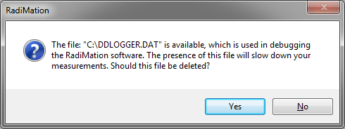
- Select no.
- Perform the measurement you have problems with.
- Close RadiMation®.
- Send the ddlogger.dat file to D.A.R.E!!, preferably in a compressed file format (Zip)
- Remove the ddlogger.dat file from your harddrive.

If you have multiple test or testsetups concerning your problem please send multiple ddlogger.dat files instead of one big file.
AD convertors
This chapter will describe the currently supported AD convertors, there minimum and maximum value. Some drivers give different information when selecting different AD convertor channels.
National Instruments 6023E 8 Analog inputs
Type of communication: IEEE.
Channels 1:
Hewlett Packard 34401A
Type of communication: IEEE.
Channel 1
Type of measurement: AC Volt
Minimum value: 0Volt
Maximum value: 1 kVolt.
Channel 2:
Type of measurement: AC Current
Minimum value: 0 Amp.
Maximum value: 3 Amp.
Channel 3
Type of measurement: DC Volt
Minimum value: 0Volt
Maximum value: 750 Volt (rms).
Channel 4:
Type of measurement: DC Current
Minimum value: 0 Amp.
Maximum value: 3 Amp. (rms)
Channel 5
Type of measurement: Resistance (Ω)
Minimum value: 0 Ω
Maximum value: 100 MΩ
Channel 6
Type of measurement: Frequency
Minimum value: 0 Hz.
Maximum value: 300 kHz
Channel 7 and 8
Not used
Hewlett Packard 54600
Type of communication: RS 232.
Channel 1:
Type of measurement: V Max.
Minimum value: 0Volt
Maximum value: 1000 Volt.
Channel 2:
Type of measurement: V Min
Minimum value: 0 Volt.
Maximum value: 1000 Volt.
Channel 3
Type of measurement: V Average
Minimum value: 0Volt
Maximum value: 1000 Volt.
Channel 4:
Type of measurement: VPP (peak-peak)
Minimum value: 0 Volt.
Maximum value: 1000 Volt.
Channel 5
Type of measurement: Frequency
Minimum value: 0 Hz
Maximum value: 100 kHz
Channel 6
Type of measurement: Period
Minimum value: 0 ms
Maximum value: 10000 ms
Channel 7
Type of measurement: Rise Time
Minimum value: 0 ms
Maximum value: 10000 ms
Channel 8
Type of measurement: Fall Time
Minimum value: 0 ms
Maximum value: 10000 ms
Hewlett Packard 3562A
Type of communication: GPIB
Channels
All the channels give the same value back.
Minimum value: 0 dB
Maximum value: 100 dB
Hewlett Packard 59313
For all the channels is 0 is maximum negative, 1024 is zero and 2048 is maximum positive.
Type of communication: GPIB
Channel 1
Type of measurement: AD channel 1
Minimum value: 0
Maximum value: 2048
Channel 2:
Type of measurement: AD channel 2
Minimum value: 0
Maximum value: 2048
Channel 3
Type of measurement: AD channel 4
Minimum value: 0
Maximum value: 2048
Channel 4:
Type of measurement: AD channel 8
Minimum value: 0
Maximum value: 2048
Channel 5 to 8
Not used.
Hewlett Packard 59313
For all the channels is 0 is maximum negative, 1024 is zero and 2048 is maximum positive.
Type of communication: GPIB
Channels
All the channels give the same value back.
Minimum value: 0 Maximum value: 100
Marconi 2305
Type of communication: GPIB
Channel 1
Type of measurement: Frequency
Minimum value: 0
Maximum value: 1000 MHz
Channel 2:
Type of measurement: AM modulation or FM frequency Deviation
Minimum value: 0
Maximum value: 1000
Channel 3 to 8
Not used.
Fluke 45 AC Current
Type of communication: GPIB
Channels
All the channels give the same value back.
Minimum value: 0 mA
Maximum value: 10.000 mA
Fluke 45 DC Current
Type of communication: GPIB
Channels
All the channels give the same value back.
Minimum value: 0 mA
Maximum value: 10.000 mA
Fluke 45 AC Voltage
Type of communication: GPIB
Channels
All the channels give the same value back.
Minimum value: 0 mV
Maximum value: 1.000.000 mV
Fluke 45 DC Voltage
Type of communication: GPIB
Channels
All the channels give the same value back.
Minimum value: 0 mV
Maximum value: 1.000.000 mV
Fluke 45 Frequency
Type of communication: GPIB
Channels
All the channels give the same value back.
Minimum value: 0 Hz
Maximum value: 1.000.000 Hz
Fluke 45 Resistance
Type of communication: GPIB
Channels
All the channels give the same value back.
Minimum value: 0 Ω
Maximum value: 100.000.000 Ω
LeCroy 9304AM Channel A,B,C,D
Select channel A for channel A, channel B for channel B etc etc.
Type of communication: IEEE.
Channel 1
Type of measurement: Minimum value
Minimum value: 0Volt
Maximum value: 353.55 Volt.
Channel 2:
Type of measurement: Maximum value
Minimum value: 0 Volt
Maximum value: 353.55 Volt
Channel 3
Type of measurement: Amplitude
Minimum value: 0Volt
Maximum value: 353.55 Volt
Channel 4:
Type of measurement: Peak to peak
Minimum value: 0 Volt
Maximum value: 707.1 Volt
Channel 5
Type of measurement: RMS
Minimum value: 0 Volt
Maximum value: 250 Volt
Channel 6
Type of measurement: Frequency
Minimum value: 0 Hz.
Maximum value: 200 MHz
Channel 7 and 8
Not used
Fluke 8840A AC Current
Type of communication: GPIB
Channels
All the channels give the same value back.
Minimum value: 0 mA
Maximum value: 10.000 mA
Fluke 8840A DC Current
Type of communication: GPIB
Channels
All the channels give the same value back.
Minimum value: 0 mA
Maximum value: 10.000 mA
Fluke 8840A AC Voltage
Type of communication: GPIB
Channels
All the channels give the same value back.
Minimum value: 0 mV
Maximum value: 1.000.000 mV
Fluke 8840A DC Voltage
Type of communication: GPIB
Channels
All the channels give the same value back.
Minimum value: 0 mV
Maximum value: 1.000.000 mV
Hewlett Packard 3478A AC Current
Type of communication: GPIB
Channels
All the channels give the same value back.
Minimum value: 0 mA
Maximum value: 10.000 mA
Hewlett Packard 3478A DC Current
Type of communication: GPIB
Channels
All the channels give the same value back.
Minimum value: 0 mA
Maximum value: 10.000 mA
Hewlett Packard 3478A AC Voltage
Type of communication: GPIB
Channels
All the channels give the same value back.
Minimum value: 0 mV
Maximum value: 300.000 mV
Hewlett Packard 3478A DC Voltage
Type of communication: GPIB
Channels
All the channels give the same value back.
Minimum value: 0 mV
Maximum value: 300.000 mV
Tektronix TDS 400 Series
Type of communication: GPIB
Channels 1 to 4
The value of the selected channel will be given back.
Minimum value: 0
Maximum value: 100
Channels 5 to 8
Not used
Tektronix TDS 500A Series
Type of communication: GPIB
Channels 1 to 4
The value of the selected channel will be given back.
Minimum value: 0
Maximum value: 100
Channels 5 to 8
Not used
Tektronix TDS 600A Series
Type of communication: GPIB
Channels 1 to 4
The value of the selected channel will be given back.
Minimum value: 0
Maximum value: 100
Channels 5 to 8
Not used
Tektronix TDS 3000 Series
Type of communication: GPIB
Channels 1 to 4
The value of the selected channel will be given back.
Minimum value: 0
Maximum value: 100
Channels 5 to 8
Not used
D.A.R.E!! Development Radimate 2 and 3
Type of communication: RS 232
Channels 1 to 8
The value of the selected channel will be given back.
Minimum value: 0
Maximum value: 16383
EPI 575
Type of communication: IEEE
Channel 1
Type of measurement: Frequency
Minimum value: 0 Hz
Maximum value: 10 kHz
Channel 2:
Type of measurement: Frequency
Minimum value: 0 Hz.
Maximum value: 100 kHz
Channel 3
Type of measurement: Frequency
Minimum value: 0 Hz
Maximum value: 1 MHz.
Channel 4:
Type of measurement: Frequency
Minimum value: 0 Hz.
Maximum value: 10 MHz.
Channel 5
Type of measurement: Frequency
Minimum value: 0 Hz
Maximum value: 100 MHz
Channel 6
Type of measurement: Frequency
Minimum value: 0 Hz
Maximum value: 1 GHz
Channel 7
Type of measurement: Frequency
Minimum value: 0 Hz
Maximum value: 10 GHz
Channel 8
Type of measurement: Frequency
Minimum value: 0 Hz
Maximum value: 100 GHz
Parallel Port Input 0x3BC and 0x378
Channel 1 to 8
Every channel represents one bit of the 8-bits port.
So when bit 4 is changing then you will see this in channel 4.