How to perform a MIL-STD RE102 Radiated Emission test
This application note explains how the MIL-STD RE102 Radiated Emission test can be performed with RadiMation®.
The "RE102, radiated emissions, electrical field" test is applicable to equipment, subsystem enclosures and all interconnecting cables and is used to verify that the electrical field emissions from the EUT and cabling do not exceed the specified requirements. Other standards are based on this test (for example DO160) and those tests are very comparable to this test.
The exact requirements and test methods for the RE102 are specified in the MIL-STD-461.
Necessary equipment
The following devices should be configured:
- Receiver
- One or more antennas
- Cables
Depending on the frequency range that should be measured, up to four different antennas may be needed.
| Antenna |
Frequency range
|
| Rod antenna |
10 kHz to 30 MHz
|
| Biconical antenna |
30 MHz to 200 MHz
|
| Double ridge horn |
200 MHz to 1 GHz
|
| Double ridge horn |
1 GHz to 18 GHz
|
Optionally
- Antenna polarizer / tower, because above 30 MHz both vertical and horizontal polarizations should be measured.
Configuration of the testsites
The configuration of the equipment is just an antenna connected with a cable to the spectrum analyser/receiver.
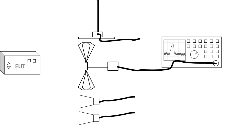
The configuration of the testsite should thus contain the following devices:
| Device name |
Tab in testsite configuration window |
note
|
| Antenna |
Devices 1 |
Antenna for the required frequency range
|
| Antenna tower |
Devices 1 |
Optional antenna tower
|
| Spectrum Analyser |
Devices 2 |
The receiver used for the test
|
| Cable preamp -> analyser |
Cables |
Cable with a correction file specified for the loss
|
As different antennas are used for each frequency range, it is best to also create and configure multiple separate testsites. Each testsite will use a different antenna, and to make the distinction between the testsites, it is best to give them different names. For example like:
| Testsite |
Antenna
|
| MIL-STD RE102 10 kHz - 30 MHz |
Rod antenna
|
| MIL-STD RE102 30 MHz - 200 MHz |
Biconical antenna
|
| MIL-STD RE102 200 MHz - 1 GHz |
Horn antenna
|
| MIL-STD RE102 1 GHz - 18 GHz |
Horn antenna
|
Perform the test
To perform the actual RE102 test, start a Radiated Emission Multiband test:
-
 Tests
Tests
- Radiated Emission
- Multiband
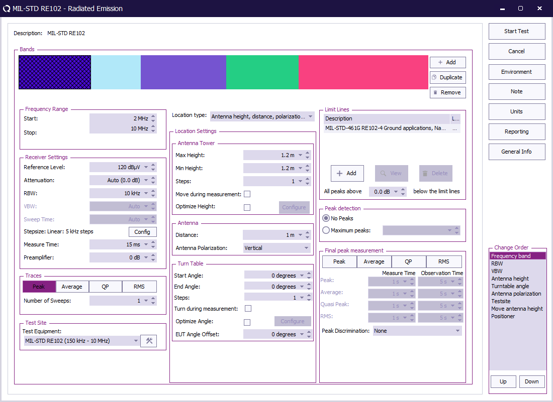
The complete test from 10 kHz up to 18 GHz has different settings for different frequency bands. All these different bands can be configured.
The test can be configured with 6 bands each using their applicable frequency range, bandwidth, polarization and used testsite (antenna).
When it is not possible to automatically switch and or position the antenna, multiple tests can be created and executed separately.
| Band |
Frequency range |
RBW |
Step size |
Measure time receiver |
Measure time FFT receiver |
Polarisation |
Testsite |
Antenna
|
| Band 1 |
10 kHz - 150 kHz |
1 kHz |
500 Hz |
0.15 s |
1 s |
Vertical |
MIL-STD RE102 10 kHz - 30 MHz |
Rod antenna
|
| Band 2 |
150 kHz - 10 MHz |
10 kHz |
5 kHz |
0.015 s |
1 s |
Vertical |
MIL-STD RE102 150 kHz - 30 MHz |
Rod antenna
|
| Band 3 |
10 MHz - 30 MHz |
10 kHz |
5 kHz |
0.015 s |
0.15 s |
Vertical |
MIL-STD RE102 150 kHz - 30 MHz |
Rod antenna
|
| Band 4 |
30 MHz - 200 MHz |
100 kHz |
50 kHz |
0.015 s |
0.15 s |
Both |
MIL-STD RE102 30 MHz - 200 MHz |
Biconical antenna
|
| Band 5 |
200 MHz - 1 GHz |
100 kHz |
50 kHz |
0.015 s |
0.15 s |
Both |
MIL-STD RE102 200 MHz - 1 GHz |
Horn antenna
|
| Band 6 |
1 GHz - 18 GHz |
1 MHz |
500 kHz |
0.015 s |
0.015 s |
Both |
MIL-STD RE102 1 GHz - 18 GHz |
Horn antenna
|
For more information regarding antenna distances, heights and required antenna positions refer to section 5.18.3.3 c. EUT testing, of the MIL-STD-461 RE102 standard.
 Start Start
|
The start frequency of the test. For example 10 kHz.
|
| Stop
|
The stop frequency of the test. For example 150 kHz.
|
| Reference Level
|
The reference level set in an analyser, not used in a receiver
|
| Attenuation
|
The attenuation set in the receiver
|
| RBW
|
The RBW set in the receiver
|
| Step size
|
The step size set in the receiver
|
| Measure time
|
The measure time set in the receiver
|
| Preamplifier
|
The preamplifier setting set in the receiver
|
| Traces
|
The type of trace set in the receiver
|
| Test Equipment
|
The equipment used for the measurement
|
| Location type
|
Set this to Antenna height, distance, polararization and angle
|
| Max Height
|
The max height for the antenna tower
|
| Min Height
|
The min height for the antenna tower
|
| Steps
|
The number of height positions to measure
|
| Move during measurement
|
If the antenna tower can move during the measurement
|
| Optimize Height
|
Find the optimal emission around a certain height
|
| Distance
|
The used antenna distance
|
| Antenna Polarization
|
Which polarization is used, Vertical, Horizontal or both
|
| Start Angle
|
The min turn table angle`
|
| End Angle
|
The max turn table angle
|
| Steps
|
The number of angles to measure
|
| Turn during measurement
|
If the turn table can move during the measurement
|
| Optimize Angle
|
Find the optimal emission around a certain angle
|
| EUT Angle Offset
|
The offset of the EUT on the table
|
| Limit Lines
|
The applicable limit lines can be added
|
| All peaks above x below the limit line
|
No peaks should be measured in RE102
|
| Peak detection
|
No peaks should be measured for RE102
|
| Final peak measurement
|
No final peak measurement is needed for RE102
|
When all parameters are configured for the RE102 test, press Start Test to perform the emission measurement.
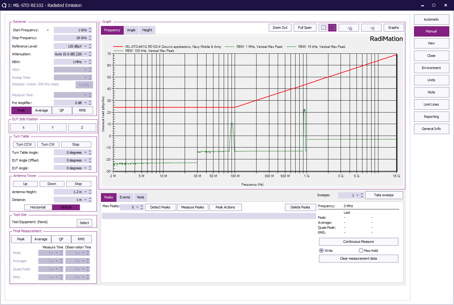
Review the test result
After performing the test it is possible to review the test data.
Conclusion
The MIL-STD RE102 test has a variety of different settings. All these settings can be easily configured in a "Test Setup File" and tested with RadiMation®.


