How to perform a MIL-STD-461 RE101 Radiated Emission test
This application note explains how the MIL-STD RE101 Radiated Emission test can be performed with RadiMation®.
The "RE101, radiated emissions, magnetic field" test is applicable to equipment, subsystem enclosures and all interconnecting cables and is used to verify that the magnetic field emissions from the EUT and cabling do not exceed the specified requirements.
The exact requirements and test methods for the RE101 are specified in the MIL-STD-461.
Necessary equipment
The following devices are necessary to execute this test:
- Receiver
- Loop sensor (Antenna)
- LISN
- Cable
Configuration of the testsite
The configuration of the testsite is a loop sensor antenna connected with a cable to a receiver.
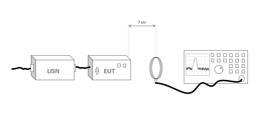
The configuration of the testsite should thus contain the following devices:
| Device name |
Tab in testsite configuration window |
note
|
| Antenna |
Devices 1 |
Loop sensor antenna for the required frequency range
|
| Spectrum Analyser |
Devices 2 |
The receiver used for the test
|
| Cable preamp -> analyser |
Cables |
Cable with a correction file specified for the loss
|
Note the lisn is only used to decouple and it is not needed to specify and configure this in RadiMation®
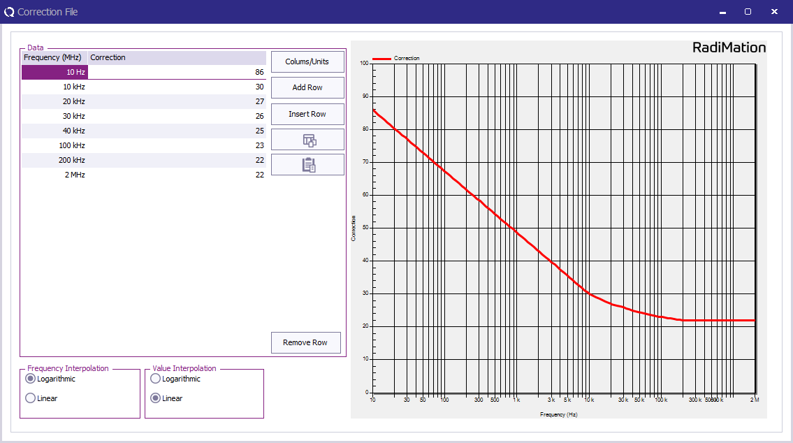
Configuration of the Loop sensor antenna
The loop antenna needs to have the correction data applied which is normally known by the manufacturer. The correction data is expressed in dBpT/uV.
In RadiMation® this can be configured by creating a correction file, which contains a 'Frequency' and a 'Correction' column. Then specify the frequencies and the correction values in the correction file. The correction values are expressed in dBpT/uV.
Convert from K [dB(S/m)] to [dBpT/uV]
Some calibration certificates contain the magnetic field factor of the loop antenna as: K [dB(S/m)].
RadiMation® expects a correction file that is expressed in [dBpt/uV].
The conversion is: 'MagneticFieldFactor [dBpT/uV] = K [dB(S/m)] + 1.984'.
The value 1.984 is often simplified to be 2.0, but 1.984 is the more accurate value.

|
| Note:
|
The relation between dBpT and A/m is: Magnetic Flux Density dBpT = dBuA/m + 1.984
In this equation, the constant 1.984 is derived as follows: The magnetic flux density, B in Tesla (T), is related to the magnetic field strength, H in A/m, by the permeability of the medium in Henry's per meter (H/m). For free space, the permeability is given as:
m0 = 4 * pi * 10E-7 H/m
B = m0 * H
Converting from T to pT and from A/m to uA/m, and taking the Log, the constant becomes:
240 - 120 + 20Log10[4 * pi * 10E-7] = 1.984 (to be exact: 1.9841972804419248955749215547977)
Also see: https://www.tf.uni-kiel.de/matwis/amat/elmat_en/kap_4/backbone/r4_1_1.html
|
|
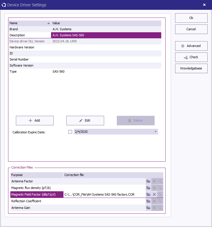
Once this correction is stored to disk, this correction file can be specified in the loop antenna driver configuration as 'Magnetic Field Factor':
Perform the test
To perform the actual RE101 test, start a Radiated Emission Multiband test:
-
 Tests
Tests
- Radiated Emission
- Multiband
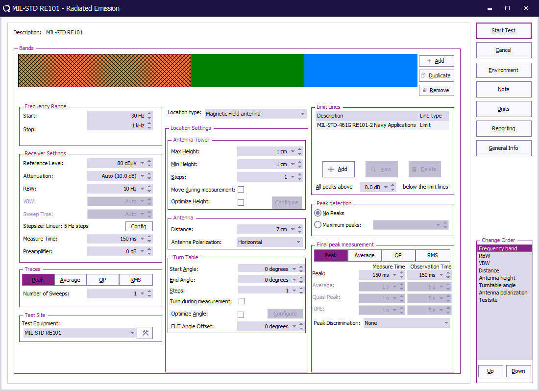
The complete test from 30 Hz up to 150 kHz has different settings for different frequency bands. All these different bands can be configured.
The test can be configured with 3 bands, each using their applicable frequency range, measure time and bandwidth.
| Band |
Frequency range |
RBW |
Step size |
Measure time receiver |
Measure time FFT receiver
|
| Band 1 |
30 Hz - 1 kHz |
10 Hz |
5 Hz |
0.15 s |
1 s
|
| Band 2 |
1 kHz - 10 kHz |
100 Hz |
50 Hz |
0.015 s |
1 s
|
| Band 3 |
10 kHz - 150 kHz |
1 kHz |
500 Hz |
0.015 s |
1 s
|
In the following test configuration an EUT for Navy Application is tested.
 Start Start
|
The start frequency of the test. For example 30 kHz.
|
| Stop
|
The stop frequency of the test. For example 100 kHz.
|
| Reference Level
|
The reference level set in an analyser, not used in a receiver
|
| Attenuation
|
The attenuation set in the receiver
|
| RBW
|
The RBW set in the receiver, see table with different bands for possible values
|
| Step size
|
The step size set in the receiver, see table with different bands for possible values
|
| Measure time
|
The measure time set in the receiver, see table with different bands for possible values
|
| Preamplifier
|
The preamplifier setting set in the receiver
|
| Traces
|
The type of trace set in the receiver, for MIL-STD RE101 a peak detector is used
|
| Test Equipment
|
The equipment used for the measurement, see table with different bands for possible values
|
| Location type
|
Set this to "Magnetic Field antenna"
|
| Max Height
|
The maximum height for the antenna tower, configuration is depending on how many positions should be measured
|
| Min Height
|
The minimal height for the antenna tower, configuration is depending on how many positions should be measured
|
| Steps
|
The number of height positions to measure, configuration is depending on how many positions should be measured
|
| Move during measurement
|
If the antenna tower can move during the measurement, not used during MIL-STD RE101 measurement
|
| Optimize Height
|
Find the optimal emission around a certain height, not used during MIL-STD RE101 measurement
|
| Distance
|
The used antenna distance, 7cm for MIL-STD RE101
|
| Antenna Polarization
|
Which polarization is used, Vertical, Horizontal or Both, above 30 MHz both polarization should be tested
|
| Start Angle
|
The minimal turn table angle
|
| End Angle
|
The maximum turn table angle
|
| Steps
|
The number of angles to measure
|
| Turn during measurement
|
If the turn table can move during the measurement, not applicable for MIL-STD RE101
|
| Optimize Angle
|
Find the optimal emission around a certain angle, not applicable for MIL-STD RE101
|
| EUT Angle Offset
|
The offset of the EUT on the table, not applicable for MIL-STD RE101
|
| Limit Lines
|
The applicable limit line can be added, in this case "MIL-STD-461G RE101-2 Navy Applications"
|
| All peaks above x dB below the limit line
|
Which level above x dB below the limit line should detect peaks, no peaks should be measured in MIL-STD RE101
|
| Peak detection
|
How many peaks should be detected automatically, no peaks should be measured for MIL-STD RE101
|
| Final peak measurement
|
It is possible to perform a final measurement on a peak with a specific detector, no final peak measurement is needed for RE101
|
When all parameters are configured for the RE101 test, press Start Test to perform the emission measurement.
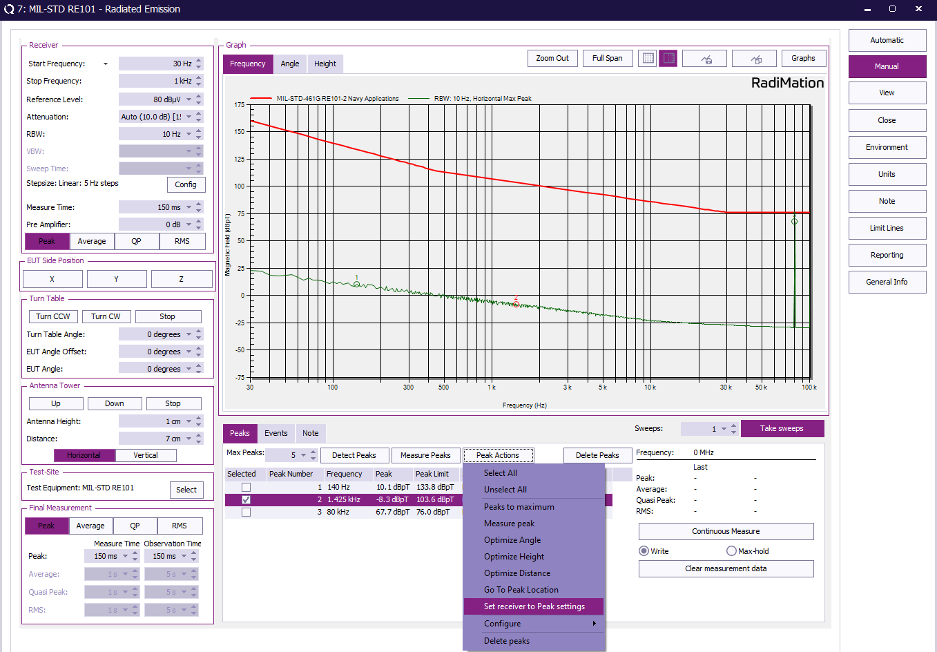
Review the initial scan and measure frequencies for maximum emission
With the the frequencies of maximum emission located, add the frequencies as peaks by clicking in the graph. A list of peaks with frequencies should appear below in the peaks tab.
To measure one single frequency:
- Select one frequency by checking one single frequency in the peaks list.
- Click Peak Actions and select Set receiver to Peak settings to set the correct measure time and RBW as configured.
- Enable Continuous Measure and move the loop antenna to find the maximum radiation as described in 5.17.3.4c(4) and 5.17.3.4c(5).
- Click Continuous Measure again to stop the measurement.
- repeat this step for each frequency.
Conclusion
The MIL-STD RE101 test is using different receiver settings depending on the frequency band. All these settings can be easily configured in a "Test Setup File" and tested with RadiMation®.


