File list
This special page shows all uploaded files.
| Date | Name | Thumbnail | Size | User | Description | Versions |
|---|---|---|---|---|---|---|
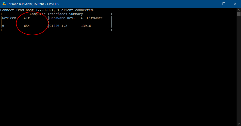
| 09:53, 28 June 2022 | LSProbeTCPServerCI.PNG (file) |  |
9 KB | Roge | 1 | |
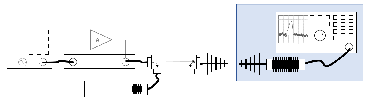
| 09:54, 27 June 2022 | HarmonicsSpectrumAnalyserAndAntennasEquipment.png (file) |  |
23 KB | Joro | The blue area contains the equipment that should be able to measure the higher frequencies of the harmonics. | 2 |
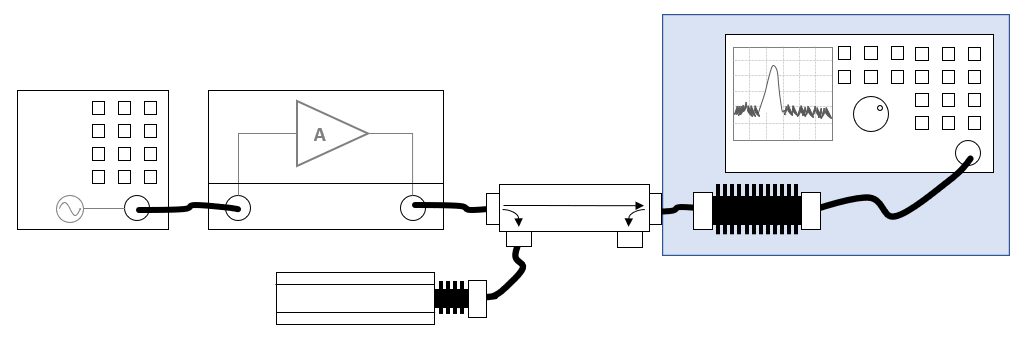
| 09:53, 27 June 2022 | HarmonicsSpectrumAnalyserAndPowermeterEquipment.png (file) |  |
20 KB | Joro | The blue area contains the equipment that should be able to measure the higher frequencies of the harmonics. | 2 |
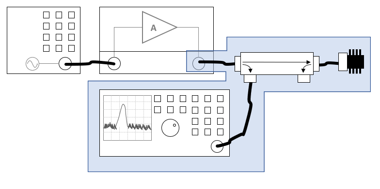
| 09:52, 27 June 2022 | HarmonicsSpectrumAnalyserEquipment.png (file) |  |
19 KB | Joro | Blue area added, to identify the equipment that is measuring the higher harmonics | 2 |
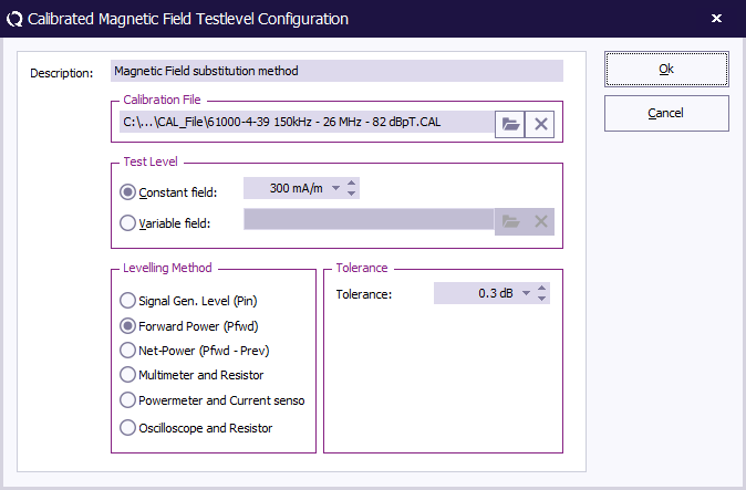
| 14:46, 20 June 2022 | MagneticFieldOnForwardPowerSubstitutionTestlevelConfiguration.png (file) |  |
22 KB | Joro | 2 | |
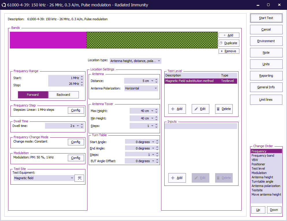
| 14:17, 20 June 2022 | RadiatedImmunityMultibandMagneticOnPowerSubstitutionConfiguration.png (file) |  |
48 KB | Joro | 2 | |
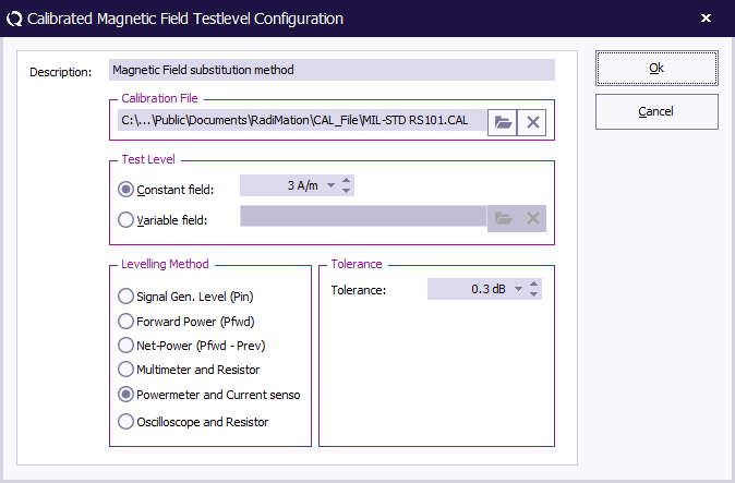
| 13:22, 20 June 2022 | MagneticFieldSubstitutionTestlevelConfiguration.png (file) |  |
22 KB | Joro | Unit is configured in A/m | 2 |
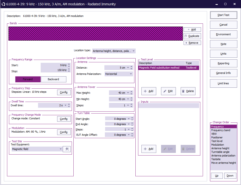
| 13:17, 20 June 2022 | RadiatedImmunityMultibandMagneticSubstitutionConfiguration.png (file) |  |
47 KB | Joro | A testlevel in A/m is specified, and antenna distance is set to 5 cm | 2 |
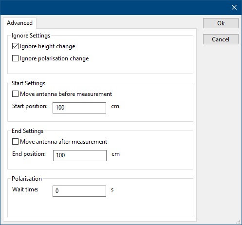
| 09:02, 16 June 2022 | DeviceDriverAntennaTowerAdvanced.png (file) |  |
6 KB | Roge | 1 | |
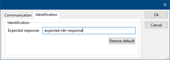
| 08:46, 16 June 2022 | DeviceDriverIdentification.png (file) |  |
3 KB | Roge | 1 | |
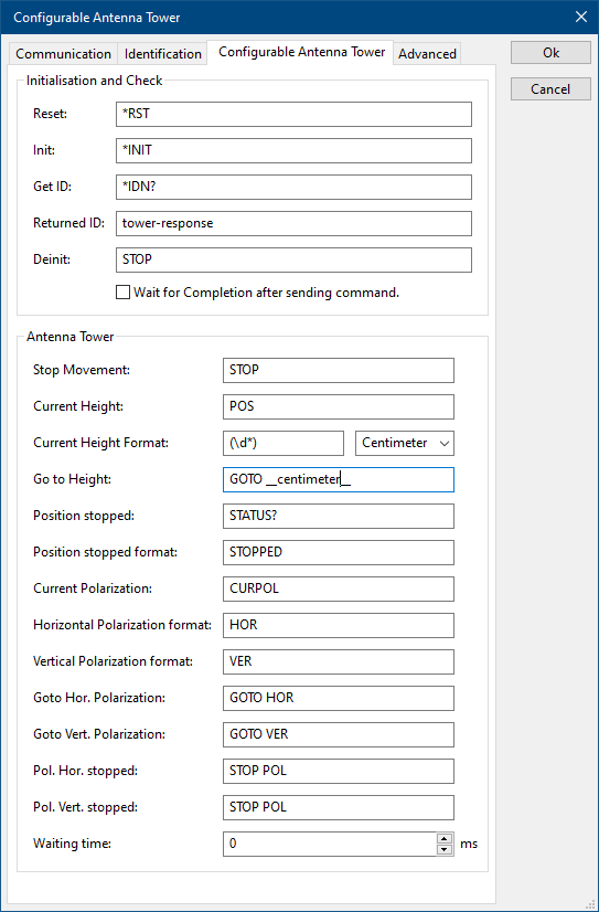
| 13:26, 15 June 2022 | ConfigurableAntennaTowerTab.png (file) |  |
14 KB | Roge | 2 | |
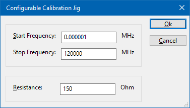
| 11:54, 15 June 2022 | ConfigurableCalibrationJig.png (file) |  |
6 KB | Joro | A screenshot of the Configurable Calibration Jig device driver. It shows the following settings: * {{ScreenElement|Start Frequency}}: 1 Hz * {{ScreenElement|Stop Frequency}}: 120 GHz * {{ScreenElement|Resistance}}: 150 Ohm | 1 |
| 11:40, 24 May 2022 | Dongle-keyhanger.jpg (file) |  |
2.27 MB | Jeru | 2 | |
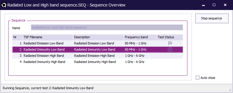
| 10:22, 20 May 2022 | Sequence overview.png (file) |  |
15 KB | Joro | 2 | |
| 09:09, 14 April 2022 | NSG4060TSConfig.PNG (file) |  |
39 KB | Jeru | 2 | |
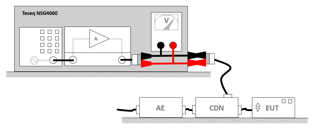
| 08:08, 14 April 2022 | TeseqNSG4060LowFrequencySetup.png (file) |  |
27 KB | Joro | Shows the setup for a IEC 61000-4-19 measurement using a Teseq NSG4060. | 1 |
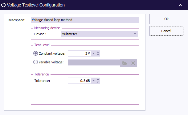
| 07:56, 14 April 2022 | NSG4060VoltageTestLevelConfig.PNG (file) |  |
11 KB | Jeru | 1 | |
| 16:30, 13 April 2022 | NSG4060TestSite.PNG (file) |  |
23 KB | Jeru | Highlight multimeter | 2 |
| 15:27, 21 February 2022 | BackupDeviceDrivers.png (file) |  |
34 KB | Joro | 2 | |
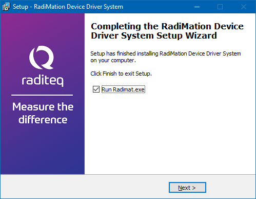
| 10:41, 21 February 2022 | DriversExeFinished.png (file) |  |
41 KB | Joro | A screenshot of the DRIVERS.EXE installation program that shows the Finished page, also including a checked checkbox to start RadiMation. | 1 |
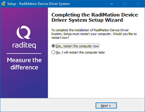
| 10:38, 21 February 2022 | DriversExeRestartPC.png (file) |  |
43 KB | Joro | A screenshot of the DRIVERS.EXE installation program that shows the Restart PC page. | 1 |
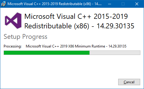
| 10:36, 21 February 2022 | DriversExeUpdatingMicrosoftRuntime.png (file) |  |
12 KB | Joro | A screenshot of the Drivers.exe installation program that is updating the Microsoft Visual C++ runtime files. | 1 |
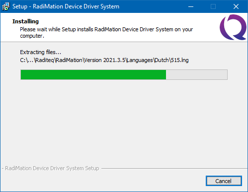
| 10:34, 21 February 2022 | DriversExeInstalling.png (file) |  |
12 KB | Joro | A screenshot of the DRIVERS.EXE that is installing files | 1 |
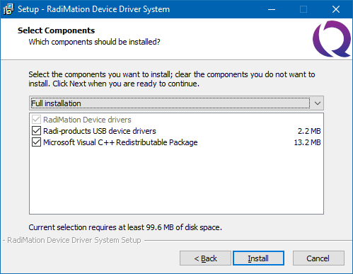
| 10:30, 21 February 2022 | DriversExeComponentsSelection.png (file) |  |
16 KB | Joro | A screenshot of the drivers.exe installation program. It shows the selection of the components. In this screenshot ALL the components are selected to be installed. | 1 |
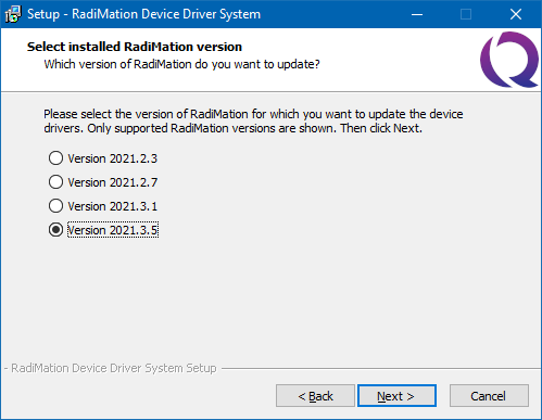
| 10:27, 21 February 2022 | DriversExeVersionSelection.png (file) |  |
13 KB | Joro | Shows a screenshot of the Drivers.exe program, where the version to be installed is shown. | 1 |
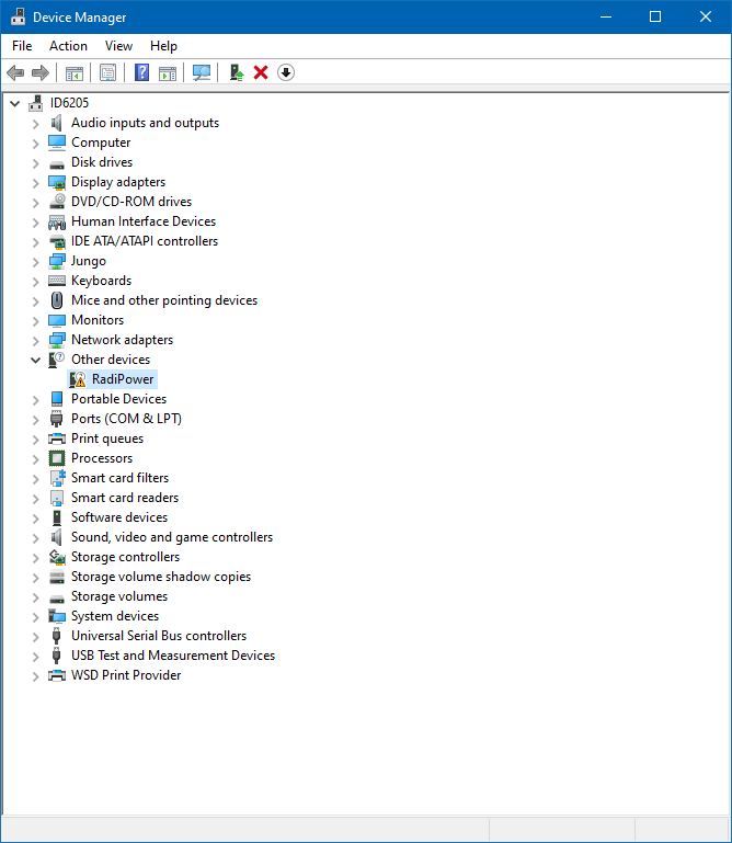
| 10:00, 21 February 2022 | DeviceManagerOtherDevicesRadiPower.png (file) |  |
33 KB | Joro | Shows a screenshot of the Windows Device Manager showing an 'unknown' device for the RadiPower in the 'Other Devices' group. | 1 |
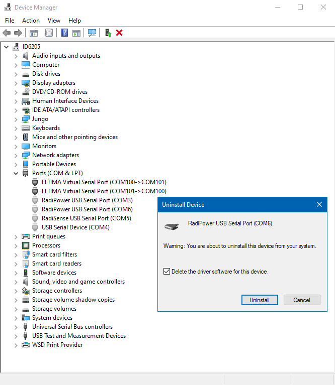
| 09:46, 21 February 2022 | DeviceManagerUninstallSerialPortDeviceAndDelete.png (file) |  |
53 KB | Joro | Shows a screenshot of the Windows Device manager, where a Radipower serial port device is being installed, also showing the checked checkbox to actually delete the software driver. | 1 |
| 09:36, 21 February 2022 | DeviceManagerShowHiddenDevices.png (file) |  |
19 KB | Joro | Shows a screenshot of the Windows Device Manager, with an activated 'Show hidden devices' menu entry from the View menu. | 1 |
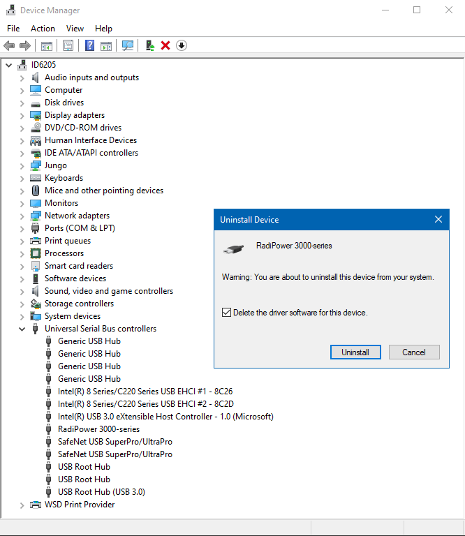
| 09:28, 21 February 2022 | DeviceManagerUninstallDeviceAndDelete.png (file) |  |
42 KB | Joro | Shows a screenshot of the Windows Device Manager to uninstall the RadiPower 3000 series, also showing that the driver software should be deleted. | 1 |
| 16:11, 17 February 2022 | NewCorrection.png (file) |  |
21 KB | Roge | 2 | |
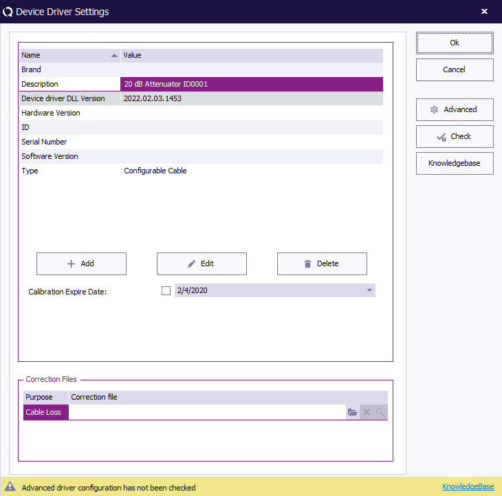
| 15:54, 17 February 2022 | CableDeviceDriver.png (file) |  |
22 KB | Roge | 1 | |
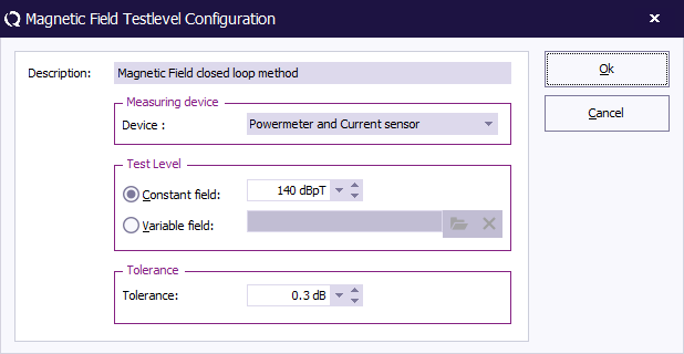
| 15:14, 3 February 2022 | MagneticFieldClosedLoopTestlevelConfiguration.png (file) |  |
12 KB | Joro | A screenshot of the magnetic field closed loop testlevel configuration window. | 1 |
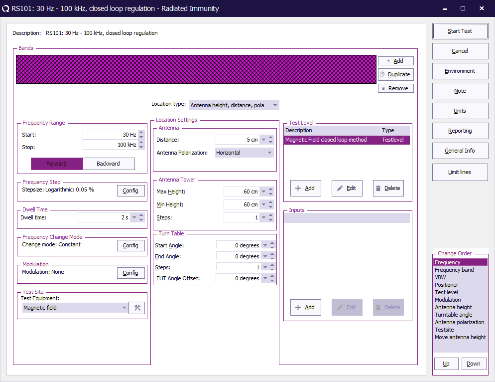
| 15:10, 3 February 2022 | RadiatedImmunityMultibandMagneticClosedLoopConfiguration.png (file) |  |
47 KB | Joro | Screenshot of a Multiband magnetic field closed loop configuration, using the settings of the mil-std RS101 | 1 |
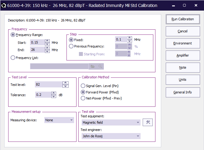
| 14:02, 3 February 2022 | RadiatedImmunityMilStdCalibrationOnForwardPowerConfiguration.png (file) |  |
23 KB | Joro | A screenshot of the Mil Std Calibration, using a regulation on Forward power. | 1 |
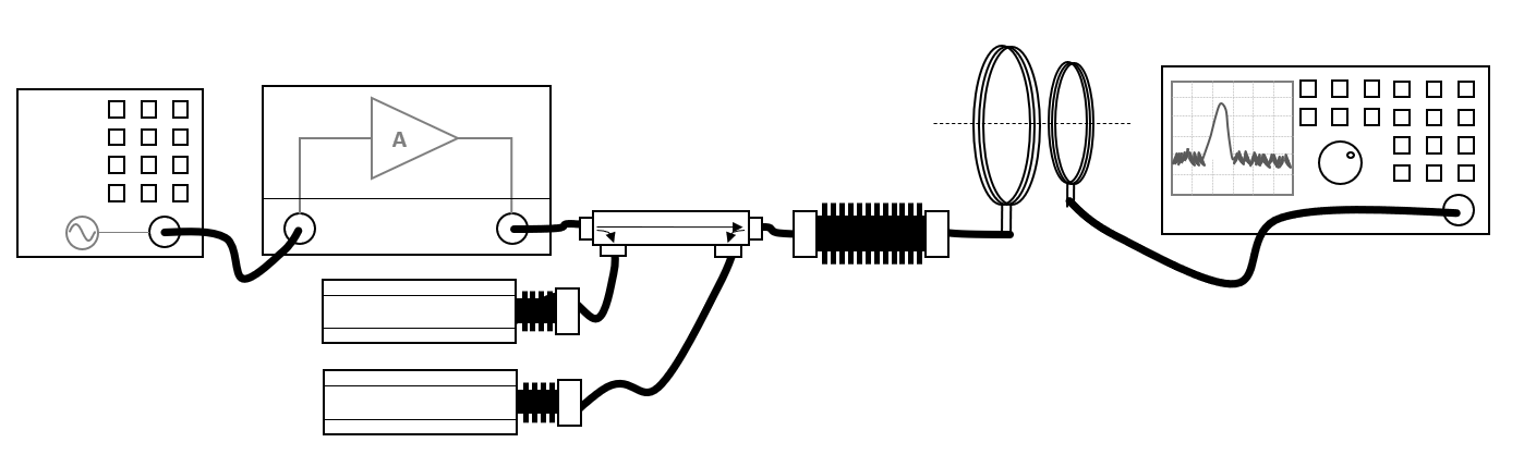
| 13:35, 3 February 2022 | MagneticFieldOnPowerTestConnections.png (file) |  |
29 KB | Joro | Shows the equipment setup for the magnetic field test, where the magnetic field is regulated on the power | 2 |
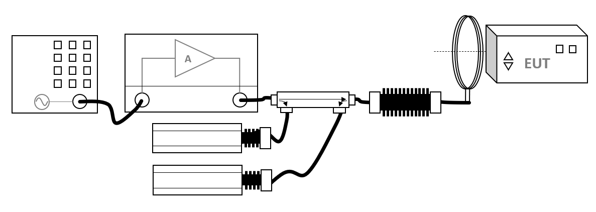
| 13:32, 3 February 2022 | MagneticFieldOnPowerSystemCalibration.png (file) |  |
38 KB | Joro | Shows the equipment setup for the magnetic field calibration, using regulation of the power. | 1 |
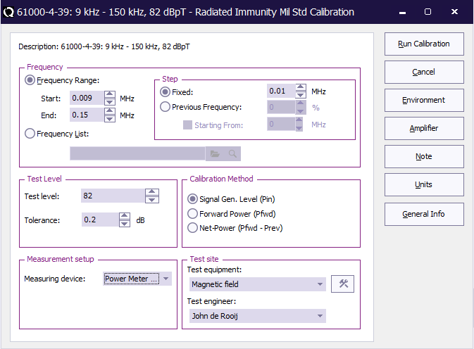
| 15:06, 1 February 2022 | RadiatedImmunityMilStdCalibrationConfiguration.png (file) |  |
23 KB | Joro | Shows the configuration dialog of a Mil Std magnetic field calibration | 2 |
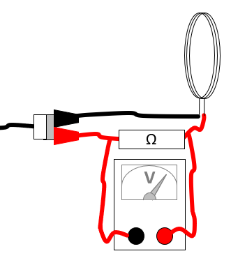
| 14:33, 28 January 2022 | MagneticFieldShuntResistor.png (file) |  |
14 KB | Joro | Equipment connections for measuring the current through a magnetic loop antenna using a shunt resistor. | 1 |
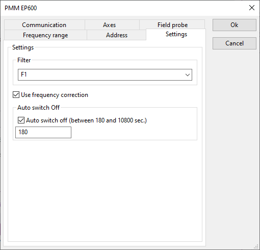
| 12:37, 9 December 2021 | PMM EP600 Settings.png (file) |  |
6 KB | Roge | 1 | |
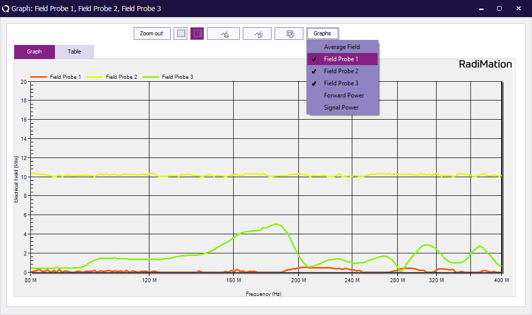
| 13:12, 1 September 2021 | TEM Calibration result graph.png (file) |  |
33 KB | Roge | 1 | |
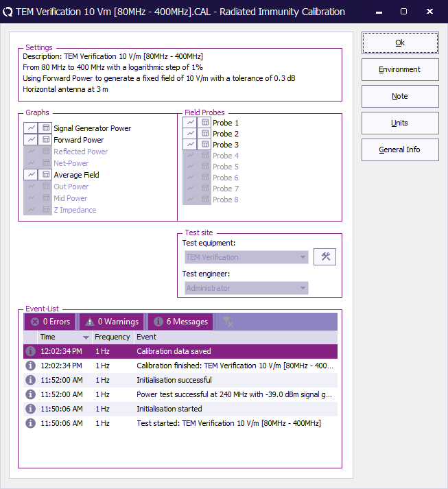
| 13:12, 1 September 2021 | TEM Calibration result.png (file) |  |
40 KB | Roge | 1 | |
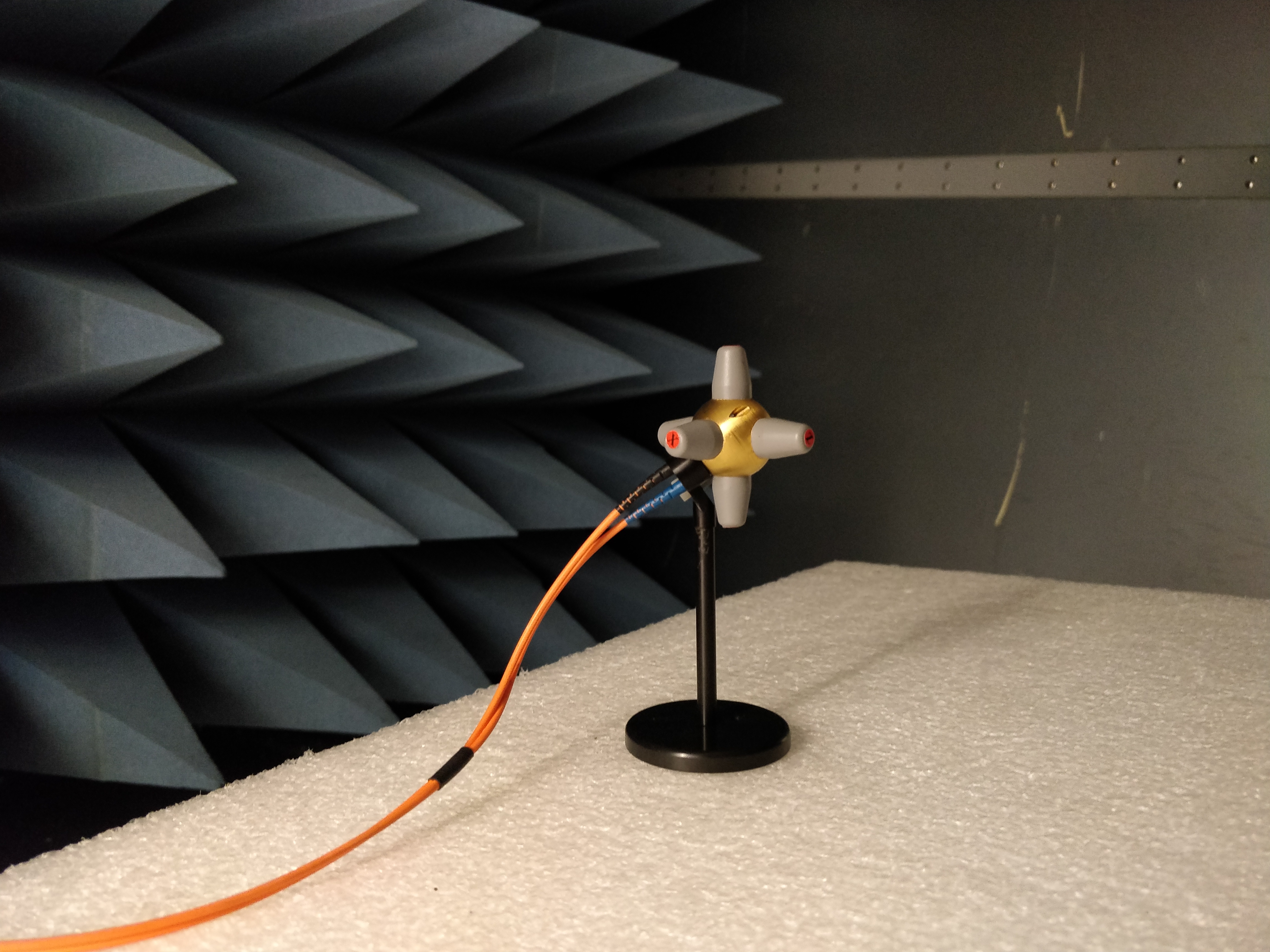
| 13:04, 1 September 2021 | XYZ Field sensor in testsite.png (file) |  |
18 KB | Roge | 1 | |
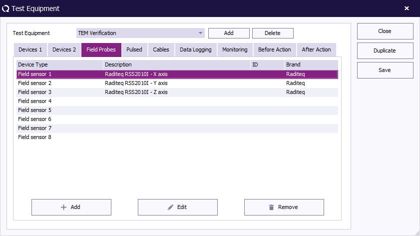
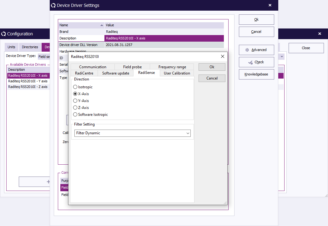
| 12:56, 1 September 2021 | XYZ Field sensors select axis.png (file) |  |
41 KB | Roge | 1 | |
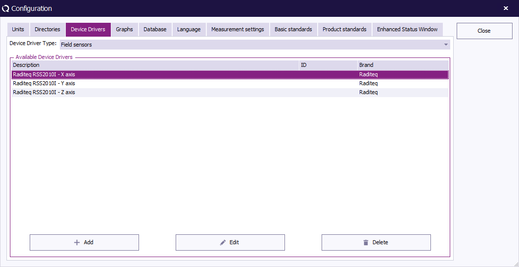
| 12:55, 1 September 2021 | XYZ Field sensors.png (file) |  |
16 KB | Roge | 1 | |
| 12:52, 1 September 2021 | Probe TEM Verification.jpg (file) |  |
3.33 MB | Roge | 1 | |
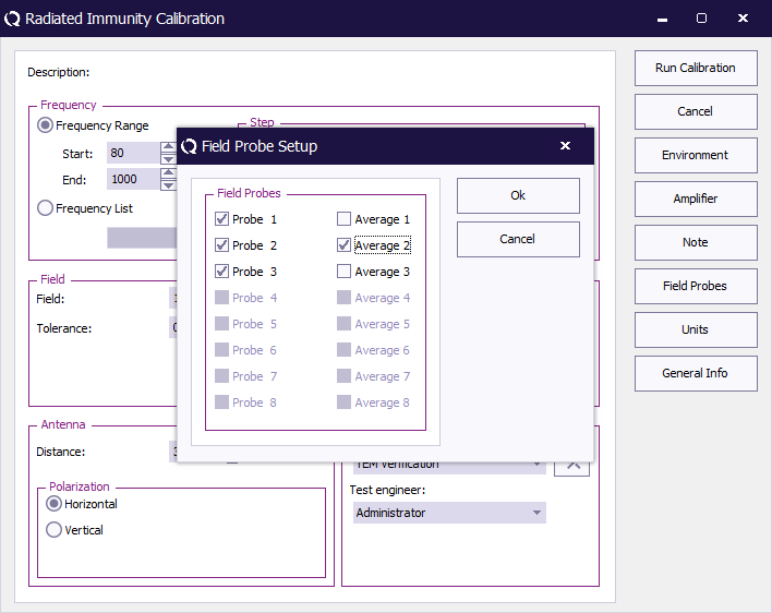
| 12:49, 1 September 2021 | Calibration probe selection.png (file) |  |
30 KB | Roge | 1 | |
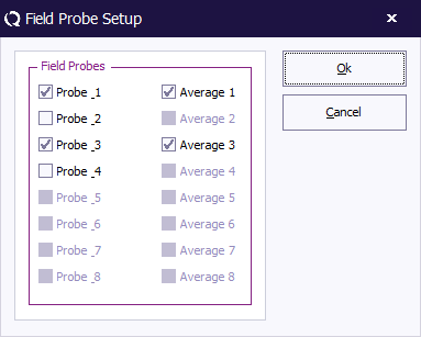
| 14:35, 19 May 2021 | OnePointCalibrationFieldProbeSetup.png (file) |  |
7 KB | Joro | Shows the Field Probe setup dialog from the Radiated Immunity 1 point calibration. It shows that only probe 1 and probe 3 are selected, and that both of them are also selected to be included in the average. Category:Screenshot | 1 |
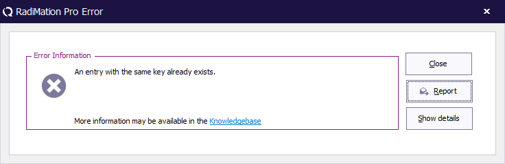
| 14:13, 5 May 2021 | ErrorPopupWindow.png (file) |  |
8 KB | Joro | 4 | |
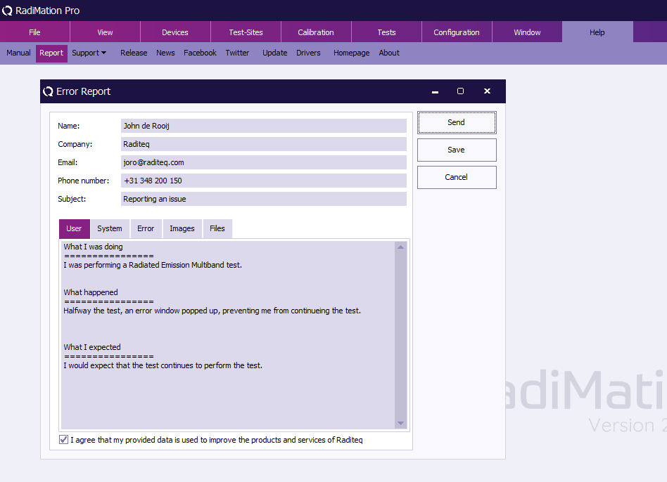
| 14:09, 5 May 2021 | ManualReportMenu.png (file) |  |
37 KB | Joro | 3 | |
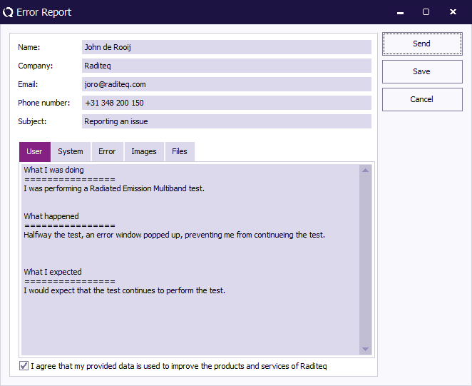
| 14:05, 5 May 2021 | ReportErrorWindow.png (file) |  |
19 KB | Joro | 5 |