File list
This special page shows all uploaded files.
| Date | Name | Thumbnail | Size | Description | Versions |
|---|---|---|---|---|---|
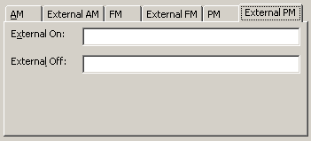
| 15:43, 1 March 2011 | Configurable Signal Generator Configuration Window Pulse Modulation External.png (file) |  |
2 KB | screenshot of the Configurable Signal Generator Configuration Window Pulse Modulation External | 1 |
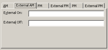
| 15:41, 1 March 2011 | Configurable Signal Generator Configuration Window Amplitude Modulation External.png (file) |  |
2 KB | screenshot of the Configurable Signal Generator Configuration Window Amplitude Modulation External | 1 |
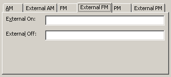
| 15:42, 1 March 2011 | Configurable Signal Generator Configuration Window Frequency Modulation External.png (file) |  |
2 KB | screenshot of the Configurable Signal Generator Configuration Window Frequency Modulation External | 1 |
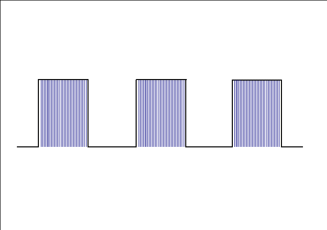
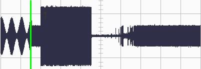
| 08:47, 10 September 2008 | PM Modulated Signal.png (file) |  |
2 KB | A display of a pulse modulated signal | 1 |
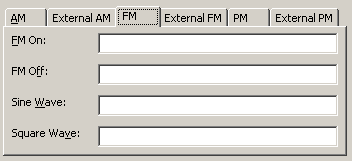
| 15:42, 1 March 2011 | Configurable Signal Generator Configuration Window Frequency Modulation.png (file) |  |
2 KB | screenshot of the Configurable Signal Generator Configuration Window Frequency Modulation | 1 |
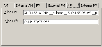
| 15:44, 1 March 2011 | Configurable Signal Generator Configuration Window Pulse Modulation.png (file) |  |
2 KB | screenshot of the Configurable Signal Generator Configuration Window Pulse Modulation | 1 |
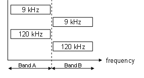
| 10:24, 16 September 2008 | Radiated Emission Multi Band Band A Band B.png (file) |  |
2 KB | screen shot of Radiated Emission Multi Band Band A Band B | 1 |
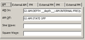
| 15:16, 1 March 2011 | Configurable Signal Generator Configuration Window Amplitude Modulation.png (file) |  |
3 KB | screen shot of the Configurable Signal Generator Configuration Window Amplitude Modulation | 1 |
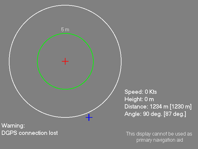
| 17:35, 18 September 2008 | Antenna Diagram Pilot Interface Stand By Window.png (file) |  |
3 KB | screen shot of the Antenna Diagram Pilot Interface Stand By Window | 1 |
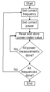
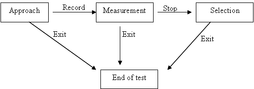
| 18:11, 20 November 2008 | Flowchart EUT Attenuation Calibration.png (file) |  |
3 KB | screen shot of the Flowchart EUT Attenuation Calibration | 1 |
| 08:25, 10 September 2008 | AM Modulated Signal No Conservation.png (file) |  |
3 KB | The amplitude presentation of a signal with AM modulation on it. | 1 |
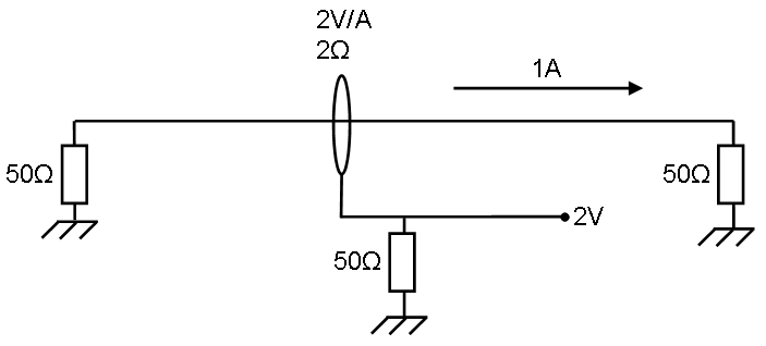
| 14:24, 26 January 2009 | Current sensor Transfer impedance Prove.PNG (file) | 3 KB | 4 | ||
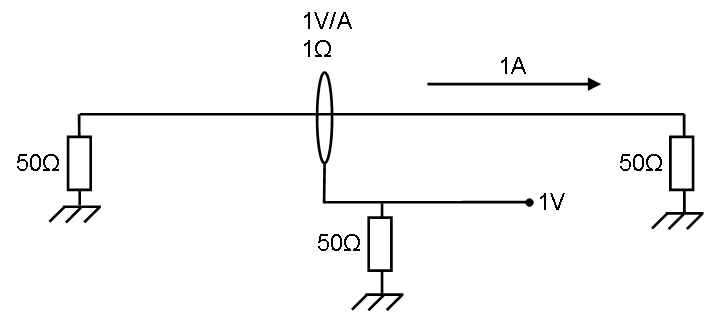
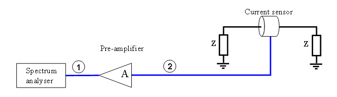
| 15:25, 26 January 2009 | Current sensor Transfer impedance example.png (file) | 3 KB | screen shot of Current sensor Transfer impedance example | 1 | |
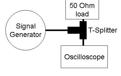
| 09:47, 12 June 2009 | Scope connection alias test.png (file) |  |
4 KB | 1 | |
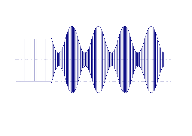
| 08:32, 10 September 2008 | AM Modulated Signal Amplitude Conservation.png (file) |  |
4 KB | Display of a AM modulated signal where the amplitude is the same as the cw value | 1 |
| 14:24, 16 September 2008 | Conducted Emission Test Setup LISN.png (file) | 4 KB | screen shot of the Conducted Emission Test Setup LISN | 1 | |
| 14:18, 12 September 2008 | Radiated Emission Test Setup Chamber.png (file) | 4 KB | screen shot of the Radiated Emission Test Setup Chamber | 1 | |
| 15:05, 12 September 2008 | Radiated Emission Test Setup Fixed Height.png (file) | 4 KB | screen shot of the Radiated Emission Test Setup Fixed Height | 1 | |
| 17:13, 18 September 2008 | Antenna Diagram Propagation Flow Chart.png (file) |  |
5 KB | screen shot of the Antenna Diagram Propagation Flow Chart | 1 |
| 17:25, 18 September 2008 | Antenna Diagram Vertical Flight Flow Chart.png (file) |  |
5 KB | screen shot of the Antenna Diagram Vertical Flight Flow Chart | 1 |
| 17:32, 18 September 2008 | Antenna Diagram Circle Flight Flow Chart.png (file) |  |
5 KB | Antenna Diagram Circle Flight Flow Chart | 1 |
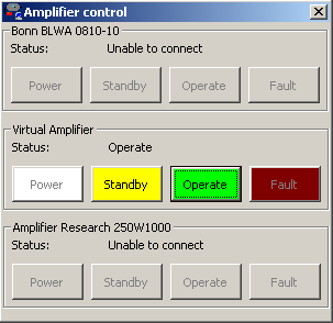
| 12:24, 23 April 2009 | Amplifier control window.png (file) |  |
5 KB | screen shot of the Amplifier control window | 1 |
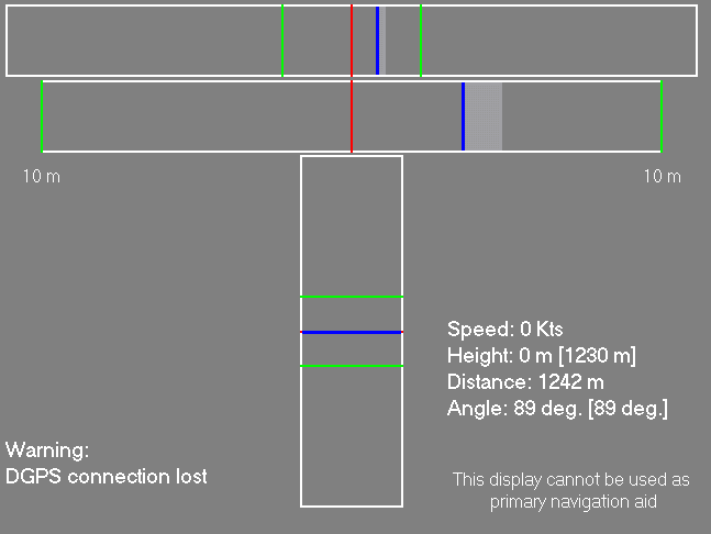
| 17:38, 18 September 2008 | Antenna Diagram Pilot Interface Propagation Flight Window.png (file) |  |
5 KB | screen shot of the Antenna Diagram Pilot Interface Propagation Flight Window | 1 |
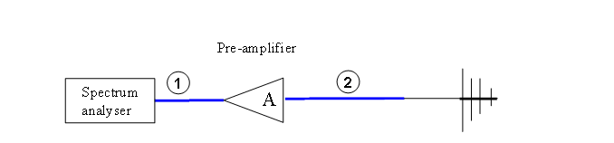
| 14:03, 17 October 2008 | Attenuation system calibration Setup.png (file) |  |
5 KB | screen shot of a Attenuation system calibration Setup | 1 |
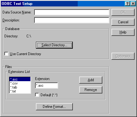
| 18:50, 20 November 2008 | ODBC text setup.png (file) |  |
5 KB | screen shot of the ODBC text setup | 1 |
| 14:25, 26 January 2009 | Current sensor Transfer impedance Ref measurement.PNG (file) | 6 KB | 4 | ||
| 14:25, 26 January 2009 | Current sensor Transfer impedance final measurement.PNG (file) | 6 KB | 3 | ||
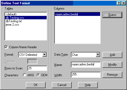
| 18:53, 20 November 2008 | Define Text format three columns.png (file) |  |
6 KB | screen shot of the Define_Text_format_three_columns window | 1 |
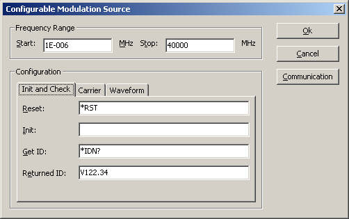
| 09:43, 21 August 2009 | Configurable Modulation Source Init and Check tab.png (file) |  |
6 KB | screenshot of the Configurable Modulation Source Init and Check tab | 1 |
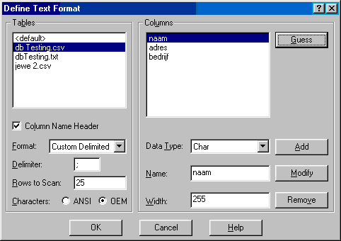
| 18:53, 20 November 2008 | Define Text format one column.png (file) |  |
6 KB | screen shot of the Define Text format one column window | 1 |
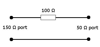
| 09:27, 18 August 2008 | 150 ohm to 50 ohm adapter.jpg (file) |  |
6 KB | 1 | |
| 14:36, 16 September 2008 | Conducted Emission Test Setup Absorbing Clamp.png (file) |  |
6 KB | screen shot of the Conducted Emission Test Setup Absorbing Clamp | 1 |
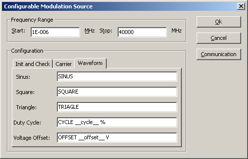
| 14:29, 21 August 2009 | Configurable Modulation Source Waveform tab.png (file) |  |
6 KB | 2 | |
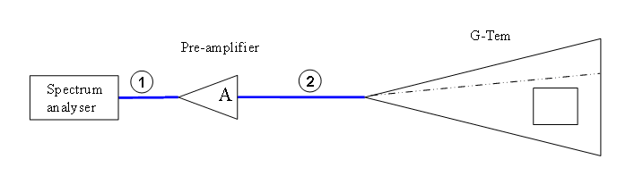
| 09:04, 16 September 2008 | Radiated Emission Test Setup GTEM.png (file) | 7 KB | screen shot of the Radiated Emission Test Setup GTEM | 1 | |
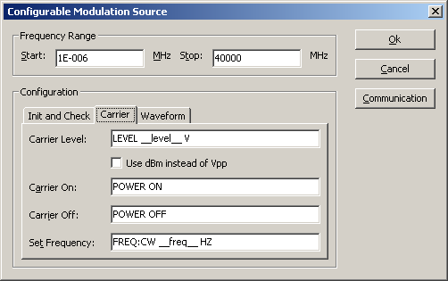
| 09:43, 21 August 2009 | Configurable Modulation Source Carrier tab.png (file) |  |
7 KB | screenshot of the Configurable Modulation Source Carrier tab | 1 |
| 17:40, 18 September 2008 | Antenna Diagram Pilot Interface Circle Flight Window.png (file) |  |
7 KB | screen shot of the Antenna Diagram Pilot Interface Circle Flight Window | 1 |
| 14:10, 14 March 2011 | Attenuation Test Setup System Calibration.png (file) |  |
7 KB | category:screenshot Attenuation Test Setup System Calibration | 1 |
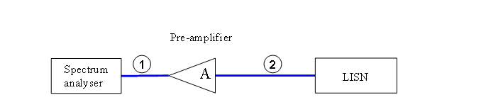
| 08:44, 8 June 2010 | Setup cdn bci calibration.gif (file) |  |
8 KB | 1 | |
| 13:11, 16 June 2008 | Clamp Calibration setup.png (file) |  |
8 KB | Clamp_Calibration_setup | 1 |
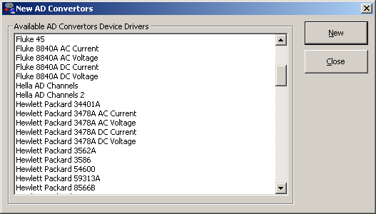
| 12:32, 19 September 2008 | New AD Convertors Window.png (file) |  |
8 KB | screen shot of the New AD Convertors Window | 1 |
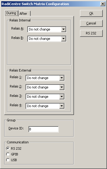
| 13:17, 13 October 2009 | Radicentre Switch Matrix configuration.png (file) |  |
8 KB | screen shot of Radicentre Switch Matrix configuration | 1 |
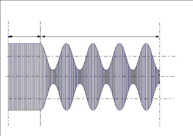
| 09:32, 12 June 2009 | Waveform AM Modulation explanation2.JPG (file) |  |
9 KB | 1 | |
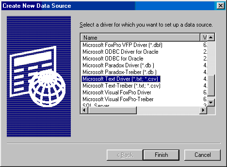
| 18:47, 20 November 2008 | Create new data source.png (file) |  |
9 KB | screen shot of Create new data source | 1 |
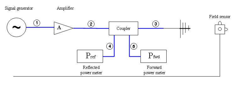
| 14:50, 29 August 2008 | Radiated Immunity Test Setup Fixed Field.png (file) |  |
10 KB | screen shot of a Radiated Immunity Test Setup Fixed Field | 1 |
| 15:39, 29 September 2008 | Radiated Immunity Test Setup Calibration 1 Point.png (file) |  |
10 KB | screen shot of the Radiated Immunity Test Setup Calibration 1 Point | 1 |
| 16:03, 29 September 2008 | Radiated Immunity Test Setup Calibration Triplate.png (file) |  |
10 KB | screen shot of the Radiated Immunity Test Setup Calibration Triplate window | 1 |
| 14:35, 29 August 2008 | Radiated Immunity Test Setup Substitution.png (file) |  |
10 KB | screen shot of a Radiated Immunity Test Setup Substitution | 1 |
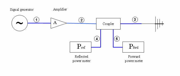
| 15:10, 29 August 2008 | Radiated Immunity Test Setup Power.png (file) |  |
10 KB | screen shot for Radiated Immunity Test Setup Power | 1 |
| 15:11, 29 August 2008 | Radiated Immunity Test Setup Fixed Power.png (file) |  |
10 KB | 1 | |
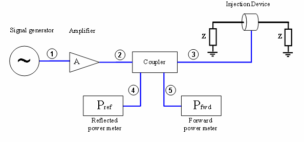
| 14:53, 10 September 2008 | Conducted Immunity Test Setup Fixed Power.png (file) |  |
10 KB | screen shot of the Conducted Immunity Test Setup Fixed Power | 1 |