Uncategorized files
Showing below up to 100 results in range #51 to #150.
View (previous 100 | next 100) (20 | 50 | 100 | 250 | 500)
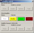 Amplifier control window.png 303 × 294; 5 KB
 AntennaSettings.png 561 × 346; 6 KB
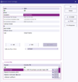 Antenna correction factor.png 732 × 765; 28 KB
 Attachments.png 1,022 × 793; 23 KB
 AttenuationGainSystemCalibration.png 960 × 318; 19 KB
 Attenuation EUT Calibration Configuration Window.png 700 × 465; 23 KB
 Attenuation EUT Calibration Result Window.png 748 × 603; 32 KB
 Attenuation System Calibration Configuration Window.png 668 × 478; 21 KB
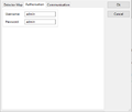 AuthorizationTab.png 513 × 436; 6 KB
 AutoPolling.png 1,013 × 553; 42 KB
 AutoResize.png 839 × 761; 26 KB
 AxisSpecificCorrections.png 774 × 372; 16 KB
 BackupDeviceDrivers.png 956 × 470; 34 KB
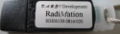 Black Dongle.JPG 500 × 142; 25 KB
 Black Dongle Sleutel Hanger.JPG 500 × 277; 40 KB
 CANoeExample.png 1,267 × 1,016; 211 KB
 CANoeSystemVariables.png 685 × 735; 45 KB
 CANoe AD Convertor signal selector.png 439 × 330; 9 KB
 CANoe CAPL messages.png 1,267 × 1,017; 72 KB
 CANoe EUT Monitoring Input Setup.png 604 × 539; 22 KB
 CANoe Simulation setup.png 1,267 × 1,017; 66 KB
 CE101 Test Configuration.png 1,049 × 725; 50 KB
 CE101 Test Result.png 1,286 × 860; 78 KB
 CE101 Test layout.png 923 × 576; 13 KB
 CE102 Test Configuration.png 994 × 725; 51 KB
 CE102 Test Result.png 1,282 × 910; 102 KB
 CE102 Test layout.png 976 × 484; 14 KB
 CS109 Test Configuration.png 1,017 × 693; 39 KB
 CS109 Test Result.png 1,277 × 850; 66 KB
 CS109 Test Setup.png 1,019 × 477; 32 KB
 CS109 Test level.png 1,011 × 507; 30 KB
 CS109 Test level configuration.png 610 × 280; 11 KB
 CS114 Calibration.png 934 × 479; 32 KB
 CS114 Calibration band 1.png 677 × 566; 35 KB
 CS114 Current Testlevel Configuration.png 755 × 420; 22 KB
 CS114 Current limit.png 610 × 280; 10 KB
 CS114 EUT Testing.png 1,126 × 498; 35 KB
 CS114 Equipment 1.png 845 × 474; 21 KB
 CS114 Equipment 2.png 845 × 474; 21 KB
 CS114 Equipment 3.png 845 × 474; 23 KB
 CS114 Modulation settings.png 690 × 370; 14 KB
 CS114 Test Result.png 1,283 × 850; 82 KB
 CS114 Test Setup.png 1,017 × 693; 40 KB
 CS114 Test level.png 1,123 × 557; 41 KB
 CS114 Verification.png 942 × 498; 30 KB
 CS114 Verification Result.png 1,283 × 850; 79 KB
 CS114 Verification Setup.png 1,017 × 693; 41 KB
 CableDeviceDriver.png 730 × 721; 22 KB
 CalibrationExpireDatabase.png 946 × 536; 9 KB
 Calibration jig factor 0 dB for 50 Ohm system.png 366 × 210; 9 KB
 Calibration jig factor 150 Ohm for 150 Ohm system.png 366 × 199; 8 KB
 Calibration jig factor 50 Ohm for 50 Ohm system.png 366 × 199; 8 KB
 Calibration jig factor 9.5 dB for 150 Ohm system.png 365 × 210; 7 KB
 Calibration probe selection.png 708 × 562; 30 KB
 Canalyzer.png 1,247 × 1,010; 103 KB
 Capture lan During.png 600 × 353; 25 KB
 Capture lan save window.png 563 × 601; 28 KB
 CarrierOffOn.png 1,233 × 823; 52 KB
 CarrierStepDown.png 1,233 × 823; 52 KB
 CarrierStepUp.png 1,233 × 823; 52 KB
 Ceyear technologies 1466H-V back.jpg 1,988 × 698; 454 KB
 Ceyear technologies 1466H-V front.jpg 1,987 × 700; 450 KB
 Change password.png 859 × 422; 18 KB
 ChangingUsernamePassword.png 1,355 × 1,017; 95 KB
 Check.png 713 × 681; 52 KB
 ChoosingUnitsForCorrectionColumn.png 770 × 529; 21 KB
 ColumnsCorrectionFile.png 819 × 525; 23 KB
 ColumnsUnits.png 1,454 × 747; 62 KB
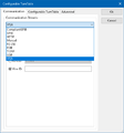
 Communication.png 524 × 496; 21 KB
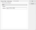 CommunicationTab.png 512 × 435; 7 KB
 Communication Settings.png 510 × 548; 7 KB
 Communicationswitch.png 510 × 465; 14 KB
 Communicationswitch2.png 510 × 465; 15 KB
 Communicationswitch3.png 510 × 465; 15 KB
 Compression.png 668 × 572; 31 KB
 ConfDvdr.png 605 × 31; 2 KB
 ConfDvdrNetworkFolder.png 194 × 46; 1 KB
 Config-Config.png 584 × 241; 34 KB
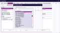
 ConfigList.png 1,063 × 678; 103 KB
 ConfigTestLevelVoltage.png 611 × 366; 12 KB
 Config default address information.png 1,024 × 250; 11 KB
 Config engineers.png 1,024 × 250; 11 KB
 Config test equipment.png 1,024 × 250; 11 KB
 ConfigurableAntennaTowerTab.png 543 × 826; 14 KB
 ConfigurableCalibrationJig.png 377 × 215; 6 KB
 Configurable Modulation Source Carrier tab.png 502 × 315; 7 KB
 Configurable Modulation Source Init and Check tab.png 502 × 315; 6 KB
 Configurable Modulation Source Waveform tab.png 502 × 323; 6 KB
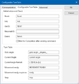
 Configurable Signal Generator Configuration Window.png 502 × 624; 11 KB
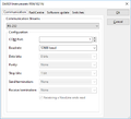
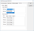
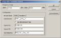
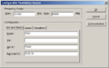
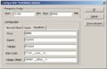
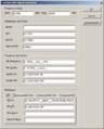
 Configurable Turn Table Configuration Window.png 510 × 548; 10 KB
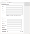 Configurable XYZ Positioner.PNG 510 × 581; 13 KB
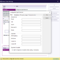
 Configurable signal generator.png 1,049 × 585; 42 KB
 Configurable signal generator edit.png 731 × 722; 32 KB
 Configurable switch matrix configuration window custom2.png 570 × 493; 21 KB


