Uncategorized files
Showing below up to 250 results in range #251 to #500.
View (previous 250 | next 250) (20 | 50 | 100 | 250 | 500)
 Enable password.png 910 × 542; 28 KB
 EnabledAmplifierControlWindowInAmplifierDeviceDriver.png 731 × 722; 27 KB
 EngineerNoPasswordSet.png 464 × 251; 15 KB
 Engineer add engineer.png 531 × 280; 6 KB
 Engineer delete engineer.png 531 × 280; 6 KB
 Engineer delete engineer confirm.png 531 × 280; 9 KB
 Engineer edit engineer.png 531 × 280; 6 KB
 Engineers admin.png 531 × 280; 5 KB
 EnhancedWindowWithTest.png 1,295 × 528; 25 KB
 Equipment Under Test EUT Information Add Cable.png 985 × 667; 28 KB
 Equipment Under Test EUT Information Edit Cable.png 984 × 667; 35 KB
 Equipment Under Test EUT Information Remove Cable.png 985 × 667; 31 KB
 Equipment under test example.png 956 × 667; 47 KB
 ErrorPopupWindow.png 736 × 240; 8 KB
 Error report screen.png 548 × 537; 18 KB
 Events problem report generator.PNG 1,162 × 811; 56 KB
- Example.docExample.doc File missing
 Explorer.png 1,380 × 579; 73 KB
 Facebook-icon.jpg 26 × 26; 606 bytes
 FieldProbePanel.png 555 × 490; 12 KB
 Field sensor Advanced settings Axis Configuration.png 510 × 490; 10 KB
 File New Limit Line.png 910 × 250; 11 KB
 File Open Limit Line.png 910 × 250; 11 KB
 File Save Limit Line.png 910 × 250; 11 KB
 File new correction file.png 1,048 × 250; 12 KB
 File new eut.png 910 × 250; 11 KB
 File open correction.png 1,048 × 250; 11 KB
 File open eut.png 910 × 250; 12 KB
 File save correction.png 1,048 × 250; 10 KB
 Formula.png 332 × 29; 1 KB
 FrankoniaWebInterface.png 633 × 459; 195 KB
 FromToClipboard.png 674 × 298; 14 KB
 HV-LVAttenuationGainEUTCalibration.png 973 × 345; 19 KB
 HV-LVAttenuationGainEUTCalibrationResult.png 661 × 511; 25 KB
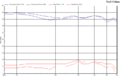
 HV-LVAttenuationGainEUTCalibrationResultGraph.png 1,013 × 808; 67 KB
 HV-LVCouplingAttenuationEUTCalibrationTSF.png 668 × 437; 23 KB
 HV-LVCouplingAttenuationSystemCalibrationTSF.png 667 × 379; 18 KB
 HarmonicTSF.png 664 × 551; 24 KB
 HarmonicsSpectrumAnalyserAndAntennasEquipment.png 1,222 × 344; 23 KB
 HarmonicsSpectrumAnalyserAndPowermeterEquipment.png 1,022 × 350; 20 KB
 HarmonicsSpectrumAnalyserEquipment.png 784 × 391; 19 KB
 Harmonics configure test.png 622 × 474; 23 KB
 Harmonics test results.PNG 990 × 524; 31 KB
 ImmunityPeakTable.png 1,305 × 895; 56 KB
 Inderface.can.png 679 × 248; 13 KB
 InjectionDevicePanel.png 376 × 218; 4 KB
 Inputs.png 1,204 × 969; 56 KB
 InsertNode.png 209 × 220; 5 KB
 InsterNodeCircle.png 241 × 183; 5 KB
 Interlock-driver-switches.png 510 × 500; 15 KB
 Interlock-radicentre-back.jpg 800 × 600; 132 KB
 Interlock-select-testsite.png 739 × 550; 30 KB
 Interlock schema.png 800 × 382; 19 KB
 IsotropicCorrections.png 771 × 373; 16 KB
 Keysight GPIB 488 Compatible mode.png 861 × 593; 20 KB
 Keysight Technologies 53220A Device Driver Settings.png 542 × 351; 21 KB
 Keysight Technologies N9048B back.jpg 4,701 × 1,933; 1.38 MB
 Keysight Technologies N9048B front.jpg 5,139 × 2,129; 1.69 MB
 LSProbe1Settings.png 762 × 484; 11 KB
 LSProbeTCPServerCI.PNG 979 × 512; 9 KB
 Limit Line Default.png 968 × 560; 25 KB
 MIL-STD-462-N1.pdf ; 239 KB
- MIL-STD-462-N2.pdf ; 93 KB
- MIL-STD-462-N3.pdf ; 5.38 MB
- MIL-STD-462-N4.pdf ; 133 KB
- MIL-STD-462-N5.pdf ; 1.18 MB
- MIL-STD-462-N6.pdf ; 385 KB
- MIL-STD-462.pdf ; 2.96 MB
 MSTeamsOpenChat.png 603 × 215; 56 KB
 MSTeamsOpenLink.png 756 × 353; 39 KB
 MSTeamsSelectScreen.png 318 × 159; 8 KB
 MSTeamsStartScreenShare.png 319 × 158; 8 KB
 MagneticFieldClosedLoopTestlevelConfiguration.png 618 × 320; 12 KB
 MagneticFieldOnForwardPowerSubstitutionTestlevelConfiguration.png 674 × 443; 22 KB
 MagneticFieldOnPowerSystemCalibration.png 1,398 × 429; 38 KB
 MagneticFieldOnPowerTestConnections.png 1,187 × 422; 29 KB
 MagneticFieldShuntResistor.png 331 × 380; 14 KB
 MagneticFieldSubstitutionTestlevelConfiguration.png 674 × 443; 22 KB
 MagneticFieldSystemCalibration.png 1,102 × 376; 37 KB
 MagneticFieldTestConnections.png 917 × 382; 26 KB
 ManualReportMenu.png 948 × 686; 37 KB
 Maturo NCD back.jpg 2,513 × 820; 1.16 MB
 Maturo NCD front.jpg 2,513 × 759; 1.09 MB
 MeasureLoop.png 771 × 530; 13 KB
 MeasurementSetup.png 468 × 206; 29 KB
 Measuring.png 1,218 × 1,003; 100 KB
 MeasuringTable.png 1,216 × 1,003; 108 KB
 MetraHitBd232.zip ; 48 KB
 Microrad-devicedriver-configuration.png 1,205 × 830; 138 KB
 Microrad-share-menu.png 789 × 648; 100 KB
 Microrad-share-running.png 789 × 648; 81 KB
 Microsoft Visual C++ 2015 Redistributable.PNG 1,133 × 220; 53 KB
 MillMegaTCPIP.png 637 × 581; 24 KB
 MkMesstechnikOnScreenDisplayCommunication.png 924 × 503; 8 KB
 MkMesstechnikOnScreenDisplayDevice.png 924 × 503; 8 KB
 MkMesstechnikOnScreenDisplaySettings.png 924 × 503; 30 KB
 Modular overview.png 428 × 503; 30 KB
 MonitoringWindow.png 972 × 653; 23 KB
 Monitoring input channel setup calculation.png 594 × 510; 32 KB
 Monitoring input channel setup calculation old style.png 594 × 510; 29 KB
 Monitoring input channel setup range.png 594 × 510; 32 KB
 MultiBandRampConfiguration.png 1,113 × 457; 18 KB
 MultibandFieldDistribution.png 992 × 765; 57 KB
- Multiband Report Template.doc ; 112 KB
 NIUpdateServiceCollapsed.png 700 × 550; 17 KB
 NIUpdateServiceSelected.png 700 × 550; 28 KB
 NIUpdateServiceUpdate.png 699 × 550; 25 KB
 NRVD Settings.png 510 × 470; 10 KB
 NRX-GPIB.jpg 868 × 359; 32 KB
 NSG4060TSConfig.PNG 1,014 × 692; 39 KB
 NSG4060TestSite.PNG 1,008 × 635; 23 KB
 NSG4060VoltageTestLevelConfig.PNG 610 × 372; 11 KB
 NSG4070.png 1,532 × 799; 58 KB
 NetworkAnalyserCalibration.png 757 × 492; 37 KB
 NetworkSetup.png 933 × 527; 27 KB
 NewCorrection.png 1,007 × 505; 21 KB
 New signal generators.png 1,049 × 585; 41 KB
 New test equipment.png 841 × 514; 25 KB
 OPCDriversExeStartPage.png 499 × 387; 14 KB
 Open Limit Line.png 999 × 561; 22 KB
 Open correction.png 999 × 561; 42 KB
 Open eut.png 999 × 561; 45 KB
 PHASE-A setup.png 1,137 × 621; 32 KB
 PMM EP600 Settings.png 510 × 490; 6 KB
 PM Modulated Signal.png 639 × 451; 2 KB
 PecosDetermineIPAdress.png 1,353 × 1,018; 124 KB
 PecosSelectLicense.png 276 × 54; 4 KB
 PecosStreamCaptions.png 1,260 × 459; 46 KB
 Persistable object not registered.png 900 × 303; 100 KB
 Phase B setup.png 1,170 × 663; 31 KB
 Pilot interface device driver configuration.png 526 × 309; 10 KB
 PolarizerPanel.png 498 × 482; 5 KB
 PolarizerSettingsPanel.png 496 × 483; 5 KB
 PowerCompressie.png 757 × 485; 15 KB
 PowerMeterConfigurationExample.png 510 × 283; 9 KB
 PowerMeterPanel.png 510 × 473; 9 KB
 Powermeterconnected.png 1,019 × 558; 38 KB
 PrgramNodeconfig1.png 692 × 255; 12 KB
 Probe TEM Verification.jpg 4,608 × 3,456; 3.33 MB
 ProgramFiles.png 671 × 43; 2 KB
 ProgrammingCorrectionTable.png 728 × 718; 51 KB
 Pulsed Imm EUTMonitoring.JPG 1,680 × 1,010; 189 KB
 Purple dongle.jpg 544 × 177; 19 KB
- QuantumChangeTileCapabilities.ppt ; 2.85 MB
 RE-ANTENNA-SPURIOUS-AND-HARMONIC-OUTPUT.png 1,105 × 805; 64 KB
 RE101 Loop configuration.png 735 × 788; 29 KB
 RE101 Test configuration.png 1,100 × 798; 66 KB
 RE101 Test layout.png 1,037 × 479; 20 KB
 RE101 Test measure peak.png 1,357 × 944; 96 KB
 RE102 Test Configuration.png 1,100 × 801; 66 KB
 RE102 Test Result.png 1,453 × 976; 88 KB
 RE102 Test layout.png 900 × 483; 15 KB
 RI-FIXED-POWER-0dBm-SignalPower.png 994 × 767; 41 KB
 RS103 Limits.png 1,007 × 505; 23 KB
 RS103 Modulation settings.png 690 × 370; 14 KB
 RS103 Test configuration.png 994 × 766; 50 KB
 RS103 Test level.png 730 × 390; 16 KB
 RS103 Test result.png 1,268 × 948; 78 KB
 RS103 Test setup.png 980 × 496; 16 KB
 RSAnalyzerPreset1.png 389 × 201; 101 KB
 RSAnalyzerPreset10.jpg 799 × 599; 117 KB
 RSAnalyzerPreset11.jpg 1,113 × 834; 279 KB
 RSAnalyzerPreset2.png 522 × 662; 51 KB
 RSAnalyzerPreset3.png 389 × 201; 101 KB
 RSAnalyzerPreset4.jpg 627 × 470; 88 KB
 RSAnalyzerPreset5.jpg 706 × 530; 119 KB
 RSAnalyzerPreset6.png 64 × 42; 4 KB
 RSAnalyzerPreset7.jpg 666 × 499; 91 KB
 RSAnalyzerPreset8.png 64 × 42; 4 KB
 RSAnalyzerPreset9.jpg 753 × 565; 117 KB
 RSUPP400PossibleConfiguration.png 945 × 555; 135 KB
 RSUPP400PossibleNumericDisplay.png 861 × 206; 42 KB
 RSUPP400RetrievableFieldsFromNumericDisplay.png 839 × 397; 121 KB
 RSW2002E Switch settings.png 497 × 482; 10 KB
 RadiAmpChannelSelectionPanel.png 497 × 483; 6 KB
 RadiGenOutputSettingsPanel.png 498 × 484; 6 KB
 RadiLogSaveAs.png 1,232 × 583; 53 KB
 RadiMationDeviceDriverSettings.png 730 × 722; 21 KB
- RadiMationInterface.zip ; 1,011 bytes
 RadiMationPathSettings.png 946 × 536; 23 KB
 RadiMationSuccesfullDeviceDriverCheck.png 304 × 126; 3 KB
 RadiatedImmunityMilStdCalibrationConfiguration.png 673 × 496; 23 KB
 RadiatedImmunityMilStdCalibrationOnForwardPowerConfiguration.png 672 × 496; 23 KB
 RadiatedImmunityMultibandMagneticClosedLoopConfiguration.png 994 × 766; 47 KB
 RadiatedImmunityMultibandMagneticSubstitutionConfiguration.png 995 × 766; 47 KB
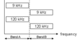 Radiated Emission Multi Band Band A Band B.png 285 × 154; 2 KB
 Radiated Immunity Substitution Configuration Window.png 835 × 735; 40 KB
 Radiated Immunity UFA Calculated Power.png 1,171 × 618; 65 KB
 Radicentre Switch Matrix configuration.png 353 × 560; 8 KB
 RadimationFree.png 210 × 46; 2 KB
 ReceiveAntennaCorrection.png 735 × 788; 29 KB
 ReferenceClockSettingsPanel.png 498 × 484; 6 KB
 RemoteVISADeviceConfig.png 495 × 482; 11 KB
 RenameProbe.png 540 × 118; 5 KB
 Report2.png 542 × 472; 23 KB
 ReportErrorWindow.png 662 × 541; 19 KB
 ReportGeneratorDocumentLocation1.png 941 × 473; 16 KB
 ReportGeneratorDocumentLocation2.png 1,005 × 716; 35 KB
 ReportGeneratorOutputLogo.png 959 × 713; 35 KB
 Report Generator Settings Window Advanced Options.png 956 × 667; 41 KB
 Report generator.png 48 × 48; 2 KB
 ResetPanel.png 498 × 484; 6 KB
 Result Enhanced Status Window enabled font color red horizontal.png 1,055 × 294; 8 KB
 ResultingCorrectionFile.png 501 × 504; 14 KB
 RiSubstitution.png 668 × 632; 46 KB
 Rohde & Schwarz FPC1000 back.jpg 4,913 × 2,233; 1.97 MB
 Rohde & Schwarz FPC1000 front.jpg 5,037 × 2,357; 2.59 MB
 Rohde & Schwarz FSP 30 back.jpg 2,516 × 1,389; 1.71 MB
 Rohde & Schwarz FSP 30 front.jpg 2,530 × 1,389; 1.77 MB
 Rohde & Schwarz UPP400 back.jpg 4,741 × 939; 693 KB
 Rohde & Schwarz UPP400 front.jpg 4,452 × 886; 609 KB
- Rssi usb driver.zip ; 14 KB
- Rssiup vxipnp 1 6.zip ; 2.96 MB
 S21InsertLossExample.png 222 × 149; 30 KB
- SCPI-99.pdf ; 4.17 MB
 SafeNet USB SuperPro-UltraPro device driver properties.png 400 × 455; 13 KB
 Save Limit line As.png 999 × 562; 22 KB
 Save correction as.png 999 × 562; 42 KB
 Save eut as.png 999 × 562; 45 KB
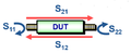 ScatteringParameters.png 546 × 222; 22 KB
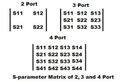 ScatteringParametersMultiplePorts.png 300 × 209; 55 KB
 Schwarzbeck BBV 9745 front.jpg 4,221 × 1,652; 1.14 MB
 Scope connection alias test.png 412 × 259; 4 KB
 Screenshot configurable amplifier configuration window.png 505 × 500; 21 KB
 Screenshot configurable switch matrix configuration window.png 570 × 493; 20 KB
 SelectExport.png 261 × 224; 3 KB
 SelectExportGraph.png 1,015 × 631; 27 KB
 SelectNewConfdvdr.png 800 × 130; 7 KB
 SelectProbe.png 496 × 449; 12 KB
 SelectTraxeforAxis.png 1,683 × 1,011; 105 KB
 Select Filter Wireshark.png 540 × 460; 42 KB
 SendTo.png 587 × 483; 17 KB
 Sentinel Setup Example.png 514 × 394; 28 KB
 Sentinel System Driver installed.png 984 × 349; 30 KB
 SeperateDrivers.png 989 × 537; 22 KB
 Sequence overview.png 792 × 316; 15 KB
 SetAxisProbe.png 510 × 490; 14 KB
 SetPrimaryBoard.PNG 866 × 685; 59 KB
 Setup cdn bci calibration.gif 605 × 275; 8 KB
- Siemens Efficient 5950 Router configuratie.pdfSiemens Efficient 5950 Router configuratie.pdf File missing
- Sma manual complete.pdfSma manual complete.pdf File missing
 SpectranUSBTCPBridge started.png 567 × 337; 10 KB
- SpectrumAnalysysis.pdf ; 3.08 MB
 Stanalonepowermeter.png 1,015 × 557; 35 KB
 Suggest Improvement by error report.png 965 × 692; 31 KB
 SwitchAmp1.png 539 × 117; 4 KB
 SwitchAmp2.png 538 × 113; 5 KB


