Performing an ETSI EN 300 328 MIMO measurement[edit]
This application note explains how a MIMO measurement as it is described in the ETSI EN 300 328 can be performed with RadiMation®. This functionality doesn't need a license, as it is also possible to perform this measurement with RadiMation® Free .
It is assumed that device drivers for the used powermeter(s) are already configured in the configuration of RadiMation®. Otherwise see RadiMation Application Note 121: Using a RadiPower powermeter stand-alone with RadiMation free, which explains in more detail how a device driver can be added for the RadiPower powermeter.
Create a new EUT-file by selecting from the menu bar:
-
 File
File
- New
- EUT
Specify a filename for the new EUT-file and select OK. A new EUT-window will now be opened.
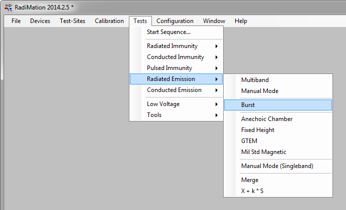
To start the Burst measurement select from the menu bar:
- Tests
- Radiated Emission
- Burst
Press New to create a new TSF-file.
The Radiated Emission Burst TSF window will now be opened in which the burst test can be configured.
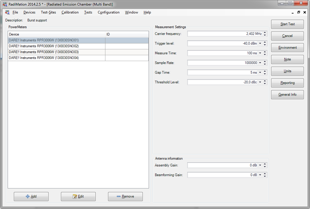
In this TSF window it is important to Add a powermeter, and to configure the measurement parameters.
The following settings are available and can be configured:
 Powermeters Powermeters
|
Shows the list of currently selected powermeters that will be used during the measurement
|
| Add
|
Allows to add one or more power meters to your test.
|
| Edit
|
Shows the device driver configuration of the selected powermeter
|
| Remove
|
Removes the selected powermeter from the list of powermeters that will be used
|
| Carrier Frequency
|
The primary frequency that will be measured by the powermeters. This frequency is used to correct the measurement result of the powermeters.
|
| Trigger level
|
Specifies the power level for the trigger level of the powermeters. The powermeters will assume that a measurement sample is part of a burst if the measurement sample is above the specified Trigger level
|
| Measurement time
|
The total time for the measurement
|
| Sample Rate
|
The sample rate that should be used by the powermeters
|
| Gap Time
|
The Gap Time specifies the minimum time that the measurement samples should be below the Trigger level to designate that period of time as a gap in the transmission
|
| Threshold Level
|
The Threshold Level defines a dB difference to the maximum measured burst value, which is used to determine if a measured burst value is designated as a transmission. Any burst that has a maximum value that is more than Threshold Level below the maximum burst value during the complete Measure time will not be designated as a transmission.
|
| Assembly Gain
|
The gain of the antenna that is normally connected to an output of the EUT. This Assembly Gain is used to calculate the total e.i.r.p. power.
|
| Beamforming Gain
|
The gain of the additional benefit of the combining of the multiple antenna's of the EUT. This Beamforming Factor is used to calculate the total e.i.r.p. power.
|
The Gap Time, Threshold Level, Assembly Gain and Beamforming Gain are terms that are explained in the ETSI EN 300 328 standard.
Pressing Start Test will start the measurement with the selected power meters and the configured parameters.
Enter a filename to save the TSF-file, so it can be used again in the future.
The measurement is then started and the results are shown in the Radiated Emission Burst Status window.
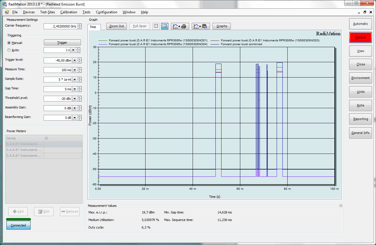
During the measurement, the resulting measurement values such as Max. e.i.r.p, medium utilisation, Duty cycle, Min. Gap time,Max. Sequence time and RMS are calculated and shown.
| Graph
|
Shows the measurement result of the burst measurement. The individual measurement of each selected powermeter will be shown, and also the combined measurement result of all the graphs. It is possible to zoom-in on the measurement data to have more measurement details.
|
| Measurement Values
|
Shows some final resulting measurement values as it is required by the ETSI EN 300 328
|
| Max. e.i.r.p.
|
Shows the maximum effective isotropic radiated power of the last combined measurement data.
|
| Medium Utilisation
|
Shows the percentage of the medium utilisation of the last combined measurement data.
|
| Duty Cycle
|
Shows the percentage of the time that a transmission was active during the last combined measurement data. This is the total TxSequence time compared to the total TxGap time.
|
| Min. Gap Time
|
Shows the smallest period of time that was designated as a gap during the last combined measurement data.
|
| Max. Sequence Time
|
Shows the largest period of time that was designated as a transmission during the last combined measurement data.
|
| RMS
|
Shows the total RMS power of the complete last combined measurement data (including the gap and transmissions). This value should be the same as the power meter reading of True RMS powermeter.
|
| Measurement Settings
|
Contains more measurement parameters that can be changed.
|
| Carrier Frequency
|
The primary frequency that will be measured by the powermeters. This frequency is used to correct the measurement result of the powermeters.
|
| Manual
|
Selects the manual triggering mode, where a new measurement is only performed when the Trigger button is pressed.
|
| Trigger
|
Starts a new measurement of all the selected powermeters with the configured measurement settings. Also the combined measurement data will be recalculated and also the Measurement Values will be recalculated.
|
| Auto
|
Selects the auto triggering mode. A new measurement will be started using the interval that is specified at the Auto setting. Also the combined measurement data will be recalculated and also the Measurement Values will be recalculated.
|
| Trigger level
|
Specifies the power level for the trigger level of the powermeters. The powermeters will assume that a measurement sample is part of a burst if the measurement sample is above the specified Trigger level
|
| Measure time
|
The total time for the measurement
|
| Sample Rate
|
The sample rate that should be used by the powermeters
|
| Gap Time
|
The Gap Time specifies the minimum time that the measurement samples should be below the Trigger level to designate that period of time as a gap in the transmission
|
| Threshold Level
|
The Threshold Level defines a dB difference to the maximum measured burst value, which is used to determine if a measured burst value is designated as a transmission. Any burst that has a maximum value that is more than Threshold Level below the maximum burst value during the complete Measure time will not be designated as a transmission.
|
| Assembly Gain
|
The gain of the antenna that is normally connected to an output of the EUT. This Assembly Gain is used to calculate the total e.i.r.p. power.
|
| Beamforming Gain
|
The gain of the additional benefit of the combining of the multiple antenna's of the EUT. This Beamforming Factor is used to calculate the total e.i.r.p. power.
|
| Powermeters
|
Shows the list of currently selected powermeters that will be used during the measurement
|
| Add
|
Allows to add one or more power meters to your test.
|
| Edit
|
Shows the device driver configuration of the selected powermeter
|
| Remove
|
Removes the selected powermeter from the list of powermeters that will be used
|
| Connected
|
Shows the connection state with the selected powermeters. Also the connection with the powermeters can be disabled or re-activated by pressing the Connected button.
|
When the measurement is finished configuration parameters can be changed if desired, and a new measurement can be triggered by pressing the Trigger button.
The measurement results can be saved into the created EUT file by pressing the Close button, which will also close the measurement window.
ETSI EN 301 893[edit]
The ETSI EN 301 893: 5 GHz RLAN contains paragraph 5.4.4 which describes the measurements of 3 different values:
- 5.4.4.2.1.1: RF output power at the highest power - Ph
- 5.4.4.2.1.2: RF output power at the lowest power of the TPC Range - Pl
- 5.4.4.2.1.3: Power density
The ‘RF output power at highest/lowest power’ can be performed using the RPR3006W powermeter with the method described above.
The ‘Power density’ measurement can NOT be performed using the RPR3006W powermeter.
For Equipment without continuous transmission capabilities and having simultaneous transmissions in both sub-bands: a spectrum analyser is also additionally needed to perform the measurement in the specific bands.
For all the other measurements that are described in the ETSI EN 301 893, a spectrum analyser is needed and another measurement technique than described in this application note should be used.


