How to perform a magnetic field close proximity test using forward power levelling[edit]
This RadiMation® application note explains how the close proximity radiated immunity magnetic field test can be performed with RadiMation®, where the levelling is done on forward power. This test is for example described in section 8.5.2 of the IEC 61000-4-39:2017.
A very similar test for the generation of magnetic field can also be done where the levelling is done on the current flowing through the transmitting loop antenna. Application Note 138: "How to perform a magnetic field close proximity test" describes how that test can be performed.
Magnetic field tests[edit]
For the generation of the magnetic field, loop antennas are used, with the exact specifications of wire thickness and number of windings, as specified in the applicable standard. Several manufacturers are providing loop antennas based on these specifications.
To characterise and validate the generated magnetic field, first a calibration is needed to determine the forward power that is injected into the loop antenna. The actually generated magnetic field is measured using another magnetic field monitoring loop connected to a frequency selective powermeter. The result of that calibration can then also be used during the actual substitution test.
Necessary equipment[edit]
The following test and measurement devices are needed:
- Signal generator
- Amplifier
- Coupler
- Forward powermeter
- Transmitting loop antenna (according the specifications of the applicable standard)
- Cables
For the calibration of the magnetic field two additional test and measurement devices are also needed:
- Receiving loop antenna (according the specifications of the applicable standard)
- Measurement receiver
Calibration[edit]
During the calibration the magnetic field transmitting loop and magnetic field monitoring loop are positioned close to each other, with a specified distance. The power injected in the magnetic field transmitting loop is then increased until the desired magnetic field level has been reached. The magnetic field monitoring loop connected to the measurement receiver is used to measure the actually generated magnetic field.
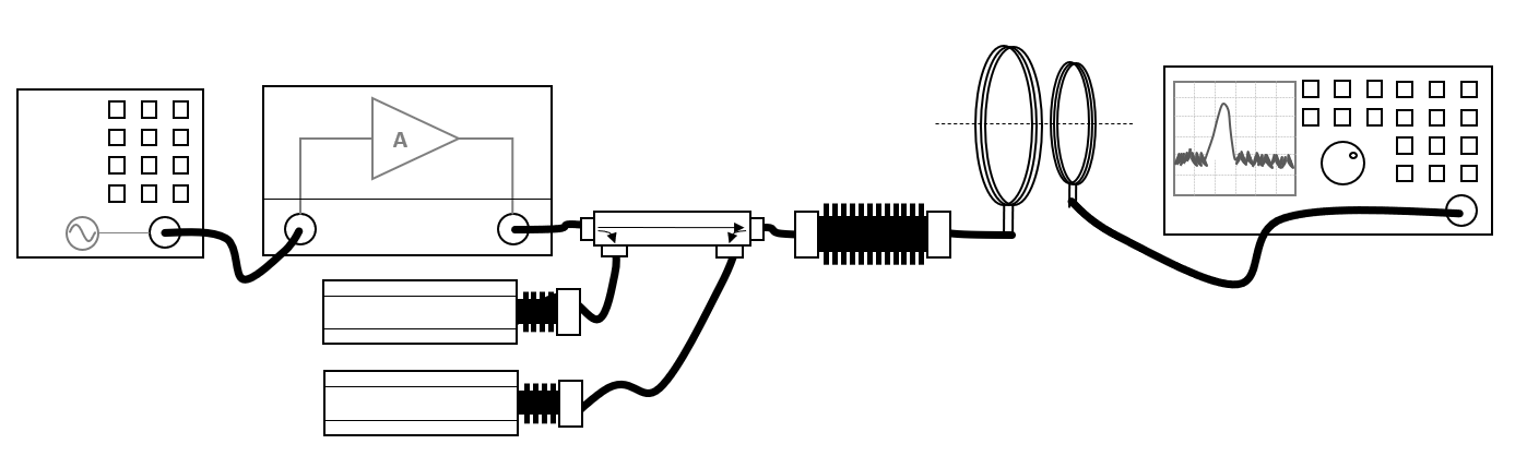
The configuration of the testsite should then contain the following devices:
| Device name |
Tab in testsite configuration window |
note
|
| Signal Generator |
Devices 1 |
|
| Amplifier |
Devices 1 |
|
| Coupler |
Devices 1 |
|
| Forward powermeter |
Devices 1 |
|
| Reflected powermeter |
Devices 1 |
Optional, only needed when a net-power calibration method is selected.
|
| Antenna |
Devices 1 |
For the magnetic field generation loop antenna
|
| Calibration Antenna |
Devices 1 |
For the magnetic field monitoring loop antenna. A Magnetic field factor (dBpT/μV) correction file should be attached to the used antenna device. See Magnetic Field Factor correction in Chapter 14
|
| Spectrum analyser |
Devices 2 |
For the measurement of the magnetic field monitoring antenna
|
The attenuator between the coupler and the loop antenna is included to reduce the impedance mismatch between the amplifier and the loop antenna. It is not necessary to include this attenuator in the testsite configuration because the attenuation of the attenuator is not corrected. The combination of the attenuator and the loop antenna (and the interconnecting cables) is what is calibrated.
The Magnetic field calibration can be started in RadiMation® by selecting from the menu:
-
 Calibration
- System Calibration
- Radiated Immunity
- Mil Std Calibration
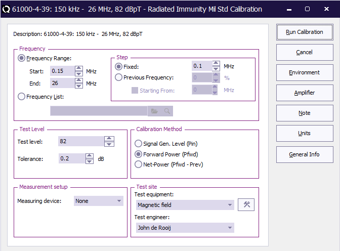
In the Mil Std Calibration dialog, the required settings can be configured. The applicable standard often specifies most of these settings.
 Start Start
|
The start frequency of the calibration. For example 150 kHz.
|
| End
|
The end frequency of the calibration. For example 26 MHz.
|
| Step Fixed
|
The frequency step that should be used to increment the frequency. For example 100 kHz.
|
| Step Logarithmic
|
The percentage of the frequency that should used to increment the frequency. For example 1 %.
|
| Test level
|
The desired magnetic field testlevel that should be calibrated. For example 82 dBpT.
|
| Tolerance
|
The tolerance (specified in dB) that should be used for the accuracy of the regulated testlevel. For example: 0.2 dB.
|
| Calibration method
|
The power level (signal power, forward power or netto power) that should be measured and stored in the calibration file. For example Forward power
|
| Measuring device
|
The device that is used for the measurement of the current. As this calibration is not done on current, None should be selected.
|
| Test equipment
|
The name of the testsite that should be used. This testsite should at least have all the required equipment.
|
| Test engineer
|
The name of the engineer who is performing the calibration.
|
Depending on the applicable standard, the test level is often specified in dBpT, dBμA/m or A/m. The Units button can be used to change which unit should be used for the Magnetic Field to specify the Test level.
When this calibration is started, the signal generator will generate every frequency, and the power injected in the loop antenna is regulated to the desired magnetic field level as it is measured by the Spectrum Analyser and the Calibration antenna. Once the desired magnetic field is regulated, the forward power is measured, which will be stored in the calibration. At the end of the system calibration a 'Save Calibration As' dialog is shown, which allows to save the result of the calibration to a .CAL calibration file.
It is advised to specify a useful location and filename for this magnetic field calibration file.
EUT measurement[edit]
Once the system calibration has been performed, the EUT can be installed and prepared. Also open an EUT file in RadiMation® to store the measurement results of the tests.
The equipment configuration that is needed for the actual test is very similar to the calibration setup.
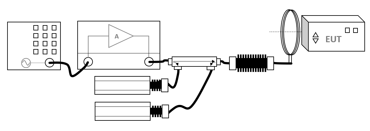
It is not necessary to include attenuator between the coupler and the loop antenna in the testsite configuration, because the combination of the attenuator and the loop antenna (and the interconnecting cables) is what is calibrated. It is important that the same attenuator and loop antenna (and the interconnecting cables) are used, as where used during the calibration.
To perform the real magnetic field close proximity test, the earlier created calibration file can be used to generate the requested magnetic field.
Just use a Radiated Immunity Multiband test by selecting from the menu:
- Tests
- Radiated Immunity
- Multiband
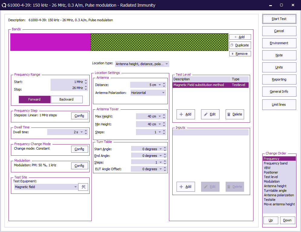
All the desired test parameters can be set in this configuration window:
| Start
|
The start frequency of the test. For example 150 kHz.
|
| Stop
|
The stop frequency of the test. For example 26 MHz.
|
| Frequency step
|
The frequency step that should be used to increment the frequency. For example 100 kHz.
|
| Dwell time
|
The dwell time that should be used at every frequency. For example 2 seconds.
|
| Frequency change mode
|
The mode that should be used to change from one frequency to the next frequency.
|
| Modulation
|
The modulation that should be applied during the dwell time at each frequency. For example Pulse modulation
|
| Test equipment
|
The name of the testsite that should be used. This testsite should at least have all the required equipment.
|
| Location type
|
The type of test that should be used. For a magnetic field test use Antenna height, distance, polarization and angle.
|
| Antenna distance
|
The used distance between the antenna and the EUT. For example 5 cm.
|
| Antenna polarisation
|
The polarisation of the antenna related to the EUT. For a loop antenna, just specify Horizontal.
|
| Antenna tower
|
The minimum, maximum and number of heights that should be moved with an automated antenna tower.
|
| Turn table
|
The start and end angle and how many angles should be measured with an automated turntable.
|
| Test level
|
The configuration of the testlevels and limits that should be used during the regulation of the test.
|
| Inputs
|
The configuration of additional inputs that should be measured during the test.
|
In the test configuration a Magnetic Field substitution method testlevel can be added. In the Magnetic Field substitution method testlevel configuration the .CAL file can be selected again, and the requested testlevel can be specified. In this configuration dialog, also the power levelling method can be selected. As the calibration file does not contain any information of the calibrated current, the current related regulation options cannot be selected.
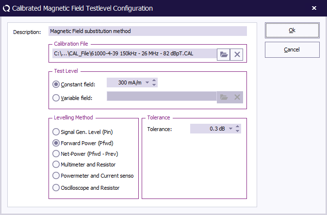
| Description
|
Specifies the name that should be used for this testlevel.
|
| Calibration file
|
The calibration file which is the result of the system calibration, and which is now used to regulate to the desired testlevel.
|
| Testlevel constant field
|
The desired testlevel for the magnetic field.
|
| Testlevel variable field
|
A correction file that should be used to for a frequency depending testlevel, which allows to do variation of the magnetic field strength over the frequency.
|
| Levelling method
|
Which power levelling method should be used to regulate the power, and thus also the magnetic field.
|
| Tolerance
|
The tolerance (specified in dB) that should be used for the accuracy of the regulated testlevel. For example: 0.3 dB.
|
Depending on the applicable standard, the test level is often specified in dBpT, dBμA/m or A/m. The Units button can be used to change which unit should be used for the Magnetic Field to specify the Testlevel constant field.
The requested test level doesn't need to be the same as the calibrated magnetic field, as RadiMation® will automatically calculate the corresponding power if another testlevel is specified.
When this test is started, the signal generator will be set to every frequency again, and the power injected in the transmitting loop antenna will be regulated to the power that is determined during the calibration, which correlates to the requested magnetic field.
Once the EUT test is finished, the results of this test is stored in the EUT file, and available as one of the performed Tests in the EUT file. Selecting the corresponding test result and pressing on Info will show the test results again.
The magnetic field transmitting loop should be located close to the EUT itself. If the EUT is larger than the illumination area of the transmitting loop, the same magnetic field test has to be repeated for example for every 50cm x 50cm area of the EUT. Also all sides of the EUT have to be tested. This can be easily done by repositioning the loop antenna, and starting the same test in RadiMation® again.
Conclusion[edit]
The RadiMation® Radiated Immunity Mil Std calibration can be used to characterise the generated magnetic field by measuring the power that is injected in the transmitting loop, and storing it in a calibration file.
The Multiband Radiated Immunity test can then use the calibration file to re-apply the required power (and thus the desired magnetic field) again. This test can then be used to test if the EUT is not influenced by the generated magnetic field.


